Showing posts with label Impedance. Show all posts

Friday, April 11, 2014

Impedance of Electrodes on my Head

Following from my previous post on figuring out how to get OpenBCI to measure the electrode-to-skin impedance, I figured that now is the time to actually measure the impedance of real electrodes on my actual skin.  I decided to try two types of electrodes: (1) disposable ECG electrodes and (2) re-usable gold cup EEG electrodes.  Here's the story of what I found...

On the left, I'm trying ECG electrodes.  On the right, I'm trying
gold cup EEG electrodes.  In both cases, I'm looking pretty sharp.

Disposable ECG Electrodes:  First, I decided to try some disposable ECG electrodes.  These are cheap and really easy to use.  They're not very good for using in your hair, but they're great for sticking on your forehead.  For the reference and bias connections, I used an ECG electrode on the mastoid bone behind each of my ears.  The picture below shows the pre-gelled, self-adhesive ECG electrodes that I used along with the clip-type ECG electrode wires (see this post for specific recommendations).

ECG Electrodes and Clip Leads That I Used on my Head

Once I stuck three of these electrodes on my head (forehead and behind each ear), I connected the lead wires to my OpenBCI V1 board using my homemade adapter.

Connecting the ECG Leads to my OpenBCI V1 Board.

After getting all connected, I activated the ADS1299's "Lead Off" excitation signal for the channel that was connected to the ECG electrode on my forehead.  As discussed in my previous post, the excitation signal is a 6 nA AC current source that the ADS1299 toggles at 31.2 Hz.  The flow of current through the electrode creates a voltage that can be measured by OpenBCI just like a normal EEG signal.  I configured my OpenBCI board to digitize the data and send it to the PC.  On the PC, I used the OpenBCI GUI to view the data in real time and to record it for post-test analysis.

A zoomed-in plot of the recorded waveform is shown on the left of the figure below.  As you can see, it has a fairly large amplitude of 508 uVrms.  This corresponds to an impedance of 120 kOhm.  That's really big!  Being surprised by that large value, I swapped the wires around so that I was measuring the electrode that I had been using as my reference (or "-") electrode.  As seen in the waveform above on the right, I got a very similar value.  That's not cool.

Example Waveforms Recorded While Using OpenBCI To Measure the
Electrode-to-Skin Impedance of (Left) the ECG Electrode on my
Forehead and (Right) the ECG Electrode behind my Left Ear.

Zooming out so that you can see more of my recording, the figure below shows about a minute's worth of data.  This is the full recording from which I made the excerpts shown above.  The longer view below shows the story of me recording data for one electrode (up to about t = 119), of how the signal goes away as I unplug and swap the electrode connections (from t = 120 to t = 132), and then how the signal returns once I am connected to the other electrode.  Again, you can see that I measured 120K from one electrode and 116K from the other electrode.

Zoomed-Out View of my Recordings Using the "Lead-Off Detection" Excitation
while Using Disposable ECG electrodes.

Gold Cup EEG Electrodes:  Because I found the impedance of the ECG electrodes to be surprisingly high, I tried using some gold cup EEG electrodes.  The picture below shows the electrodes and the conductive electrode paste that I used.  Like with the ECG electrodes, I put one of these on my forehead, one on the bone behind my left ear for the EEG reference and one one the bone behind my right ear as the EEG bias.

Gold Cup EEG Electrodes and Ten20 Brand EEG Paste

After putting on the electrodes, I activated the "Lead Off" excitation, like before.  Some examples waveforms from the data that I recorded are shown below.  As expected, the waveform shape is the same as seen before, but the amplitude is different, which reflects the fact that the impedance of the electrode-to-skin interface is different.
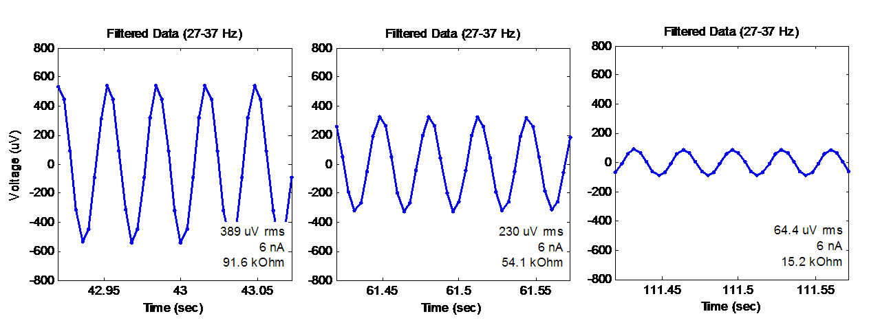
Waveforms Recorded from the Gold Cup Electrodes During the "Lead Off" Excitation.

Notice that the three plots show decreasing amplitude, which means that I was getting better contact and less impedance in each case.  What was happening?

Well, for the first waveform (the one on the left) was shows what I measured when I first attached the electrodes.  It shows an RMS amplitude of 389 uV, which corresponds to an impedance of approximately 92 kOhm.  This was still higher than I wanted, so I fiddled with the electrode and pushed it into my skin to try to make better contact.  That's when I got the middle graph -- 230 uV and 54 kOhm.  Finally, I pulled off the electrode, replaced the conductive paste, and really pressed and twisted the electrode against my skin.  That's when I got the graph on the right -- 64 uV, which corresponds to 15 kOhm.  That is more like the kind of value that I was hoping to see.

Below is a zoomed-out plot of the whole scenario with the gold cup electrode.  Again, this is the full record from which I made the excerpts above.  On the left side of the plot, you can see the 389 uV, 92 kOhm condition that I showed before.  Then, you can see my multiple attempts at re-seating and re-pasting the electrode.  Finally, at the end, I finally got to the 64 uV /  15 kOhm condition.  So, while it does take some effort, it is possible to improve the electrical contact between the electrode and your skin.

Zoomed-Out View of my Recordings Using the "Lead-Off Detection" Excitation
while Using the Gold Cup EEG Electrodes

Why Were the ECG Electrodes So Bad?  This experiment started with the ECG electrodes, which yielded a very high impedance of 120 kOhm.  If I could only use the ECG electrodes, this high impedance value would have prompted me to remove the electrode, to scrub the skin (hard!) with alcohol and a rough pad, and then to attach a new electrode.  Maybe this would have worked to lower the impedance, or maybe not.  If it would not have helped, the problem could be that my ECG electrodes are really old.  If you look really closely at my picture showing the electrodes, you'll see that the ECG packet in the background shows a date of "June 2012".  Yikes!  I have a friend who is developing a hacker-friendly EMG system (go FlexVolt!) who has mentioned to me that he has seen difficulty when using old ECG electrodes.  So, I'm thinking that maybe disposable electrodes have a limited shelf life...and that 2 years is maybe too old.

Next Steps:  With the impedance monitoring working on my OpenBCI board, I'm hoping that it will enable me to make more reliable EEG recordings. Hopefully, getting good low-impedance connections will increase my chances of detecting those low-level signals that have vexed me with their sometimes-I-see-them and sometimes-I-don't behavior.  In particular, I'm thinking about those pesky Mu waves that have been hard for me!  We'll see if this impedance checking can help...

Thanks for reading!

Follow-Up: Want to get the data from this post?  Try downloading it from my github!

Thursday, April 10, 2014

OpenBCI: Measuring Electrode Impedance

An important driver of EEG signal quality is how well the electrodes are electrically connected to the skin.  Common clinical and research guidance often says to use skin cleansing and skin abrasion to get the electrode-to-skin impedance down below 10 kOhm or even 5 kOhm.  If you don't, you can get noisy or unrepeatable measurements.  Most EEG systems allow you to measure the impedance at each electrode.  The OpenBCI system that I have been helping to develop is also capable of doing this (see other's work on using the ADS1299 to measure impedance) but I have not taken the time to figure out how to use it.  Until now...

Measuring Electrode Impedance Using the ADS1299's "Lead Off" 6nA Current Source

Impedance from Voltage and Current:
  The main idea with measuring the impedance of the electrode-to-skin interface is for the EEG system to inject a known current through the electrode and to measure the resulting voltage difference.  Since V = I*R, you can easily compute impedance "R" by taking the measured voltage "V" and dividing by the known current "I".  Pretty easy, right?  Well, how do you inject the current?  And how do you measure the voltage across the electrode-to-skin interface?

Injecting the Known Current:  The core of the OpenBCI board is the ADS1299 integrated circuit from Texas Instruments.  It has a feature called "Lead Off Detection" that does this trick of injecting a known current into each electrode.  As you can see in the figure above, a very small current (shown as 6 nA) is forced into the electrode line by a current source built into the ADS1299.  So, no matter how much resistance or impedance is between the current source and ground (within reason, of course), the system forces 6 nA through the electrode to ground.

What is Ground?  Unless you are sitting in salt water or touching something big and metal, it is unlikely that your body is connected to ground.  To address this, an EEG system often provides an extra connection in addition to the regular electrodes.  This extra connection is usually called something like "bias", or "driven ground", or "driven right leg (DRL)".  The purpose of this connection is to keep your body's DC voltage level within an acceptable range and to keep any common-mode AC signals in your body minimized.  Therefore, the bias line will act to source or sink whatever current as necessary (within reason) to minimize your DC and common-mode AC signals.  As a result, for the 6nA current that we are injecting, "ground" is the bias driver, as shown in the figure above.

Making a Mental Model of Where the Current Goes

Measuring Just the Electrode-to-Skin Voltage:   If the bias driver is our ground, the figure shows one way to model where the current goes.  Note that the current passes through several unknown impedances on its way to ground.   How do we evaluate just the impedance of the "+" electrode's interface to the skin?  The answer is to remember that an EEG system measures the voltage between its "+" input and its reference (or "-") input.  Because of the high-input impedance of the differential amplifier, no current flows into the "-" electrode line, so none of its impedance elements matter (for the purpose of this measurement).  Therefore, we can easily measure just the voltage drop across the first three elements -- the 5K in-series resistor, the electrode-to-skin impedance, and the impedance of a portion of the human body.  Because the series resistor is known, and because the impedance of the body is too small to matter, we have only one unknown remaining -- the impedance of the electrode-to-skin interface.

Calculating the Impedance:  The model above shows the electrode-to-skin interface as a simple resistor.  While this is not quite right (it does have a capacitive component as well), we can use this model to roughly estimate the number we need.  Following from the basic V = I*R, we shuffle the terms to get R = V/I.  We know both "V" (the measured voltage drop) and "I" (the known 6 nA current), so we easily get "R".  The only trick is to make sure that you're using compatible units for voltage and current.  In my case, I'm measuring the voltage as an *RMS* value (not an amplitude value).  My current value (6 nA), however, is an amplitude value, not an rms value.  So, to make the units compatible my calculation must includes a factor of sqrt(2) to convert RMS into amplitude:

R = (Measured Voltage * sqrt(2))/(Known Current) 

Finally, remember that the "R" here is the the series resistance of the electrode-to-skin interface plus the 5K resistor built into the OpenBCI board.  So, to get the impedance of just the electrode-to-skin interface, you need to subtract 5K.

Testing on OpenBCI:  To confirm that this all works in real life and not just on paper (or, um, just on a blog page), I used one of my OpenBCI boards to test it out and confirm that it works.  The simplest test that I could devise was to use clip leads (see picture below) to jump together the electrode connectors.  Specifically, I connected four of the "+" electrode connectors to the single reference (ie,"-") electrode connector, which is then jumped to the bias electrode connector.  This configuration eliminates all of the electrode-to-skin impedances and the human body impedances.  The only impedances remaining are the 5K series resistors.  Hopefully, when I do my voltage measurements and divide by the 6 nA current, I'll get a number close to 5K.


Testing the Impedance Measurements on an OpenBCI V1 Board.
The colored wires are directly connecting  (ie, shorting) the electrodes
to the reference electrode and to the bias electrode.

Configuring for the Test:  Because I only had a few clip leads, I could only jumper four of the eight "+" electrode connectors.  As a result, when I ran OpenBCI, I only activated channels 1-4.  I configured the "Lead-Off Detection" settings to generate a 6 nA current source at a frequency of 31.2 Hz.  I then started to activate the current sources on the "P" side of each EEG channel.  I saw that I could activate and deactivate the signal on any given channel without affecting the signals seen on the other channels.  Excellent.

Screenshot of the OpenBCI GUI when running an impedance test on channels 1-4.  Click to zoom.
Note that ~31 Hz test signal is present in the first four channels
and that the resulting per-channel impedance is 5.4-5.8 kOhm.

Results:  With all four current sources active, I got the results seen in the screenshot above.  As you can see (click to enlarge), a 31 Hz signal is present in the first four channels.  You can see this in the time-domain montage on the right and in the frequency spectrum plot in the bottom-left.  On the time-domain plot, you can see that my labels indicate that the voltage induced on each EEG channel is between 23.0 uVrms and 24.5 uVrms.  Using my equation from a few paragraphs back, this yields impedance estimates of 5.43 to 5.77 kOhm.  Since I'm expecting to see the resistance of each channel's 5 kOhm resistor, this corresponds to an error of 9-15%.  Given that the ADS1299 datasheet says that the "known" current is only known to +/- 20%, I find my result to be very satisfying.  I'm feeling pretty happy right now.

Super-Advanced Topics:  With the method described above, you can measure electrode-to-skin impedance of the electrodes attached to the "P" inputs of this system.  The question remains on how to measure the impedance of the reference electrode (which is attached to the "N" inputs) and of the bias electrode.  The short answer for the reference electrode is that you can use the similar ADS1299 feature for the "N" channel (as long as you do not use SRB1 as a cheater way to mux the REF to all of the "N" inputs, which is what we do in OpenBCI V1).  And the short answer for the bias electrode is that the ADS1299 can detect if it is attached, but it cannot measure its impedance.  Luckily, the impedance of the bias electrode is not as relevant.

Overall Success:  So, I'm feeling pretty good about getting this impedance measuring to work.  The code for implementing this has been pushed to the OpenBCI GitHub.  The next step is do do some impedance measurements using actual electrodes on my actual head.  Look for a follow-up post!

Follow-Up:  I measured the impedance using disposable ECG electrodes as well as re-usable gold cup EEG electrodes.  You can see the results here:

Follow-Up: I linked this post to answer a question on the Texas Instruments user forums (regarding the Texas Instruments ADS1299 chip at the heart of OpenBCI).  This post was recognized by TI for a TI Community Award, Aug 2015.  Thanks, TI!