Showing posts with label BrainBay. Show all posts

Sunday, January 5, 2014

OpenBCI Driver in BrainBay

Recently, I got an email from Chris, the primary developer behind BrainBay.  He had seen my earlier post, where I'd found a way to get OpenBCI to send data to BrainBay for live visualization and processing.  I was able to make it work by forcing OpenBCI to mimic the data format used by OpenEEG.  Since OpenBCI is more capable than OpenEEG (OpenBCI has more channels and higher bit depth), fitting myself into the OpenEEG format was not an optimal solution.  Well, Chris saw an opportunity to remedy the situation, so he wrote an OpenBCI-specific driver for BrainBay.  Now, OpenBCI can send all 8 channels of data in full resolution to BrainBay!  Thanks, Chris!

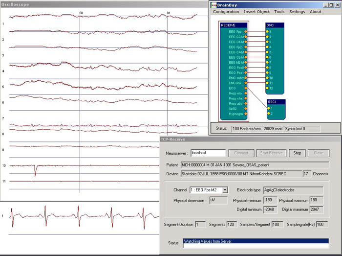
Recording my ECG into BrainBay Using  the new OpenBCI-Specific Driver.
I'm holding the electrodes between my fingers.

Below is a screen shot of the BrainBay hardware setup screen using the new OpenBCI driver.  It's pretty straight-forward...select the COM port and select the baud rate for the communication and you're done.

Setup Screen in BrainBay for the New OpenBCI Driver
 Right now the driver assumes that you are using a 250 Hz sample rate (which is what OpenBCI's Arduino software defaults to), but if you tell OpenBCI to run faster, BrainBay lets you change that.  Simply go to BrainBay's "Options" menu and select "Application Settings".  There, you can change the sample rate to however you've configured your OpenBCI board.

Once Chris made this OpenBCI driver, we had to test it out to make sure that it worked.  Since Chris didn't have an OpenBCI board, he couldn't test it himself.  So, he'd point me to his GitHub, I'd download his latest version of BrainBay, and I'd test it for him.  An important part of testing is doing things repeatably.  So, I added a mode to the OpenBCI software where it would output simple test waveforms instead of the real EEG data. (It is true that the ADS1299 has a bunch of test signals built-in, but none let you do different waveforms per channel.  That's what I coded up for OpenBCI.)

Below is a screen shot of BrainBay after we got the OpenBCI driver all debugged.  The synthetic test waveforms that were being output by OpenBCI are the simple ramp waves shown below.  Once we finally got it to look like this, I was so happy!

Confirming Correct Operation in BrainBay via Synthetically Generated Data from My OpenBCI Board.

With basic operation confirmed, I wanted to test it with real biosignals.  So, I did what I always do as my first test...ECG.  As seen in the picture at the beginning of this post, I used a couple of really basic electrodes connected to an OpenBCI V1 board.  To get my ECG, I simply held those basic between by finger tips (I licked my finger tips to increase their conductivity).  Generally, this is a really bad way to do an ECG...the muscle artifact from actively holding the electrodes can swamp your signal.  But, with a very light tough, it can be good enough to prove that that the system is working.  And it was working.  A screen shot of my ECG is shown below.  This is a pretty decent looking ECG trace...it's got a nice little P-wave, a sharp R-wave, and a nice rounded T-wave.  Very fine.

Recording my ECG From OpenBCI Using the New Driver in BrainBay.  Looks good!

So, unlike my previous time posting about BrainBay, this latest recording is all at OpenBCI's native capabilities.  There was no dumbing it down to fit within OpenEEG's data format.  With Chris' latest version of BrainBay, you can now use all 8-channels that OpenBCI generates at OpenBCI's full 24-bit resolution.

Latest BrainBay on GitHub: https://github.com/ChrisVeigl/BrainBay

Thanks, Chris!

Monday, November 4, 2013

Collecting ECG with my EEG setup

When playing with a new EEG system (home-built or purchased), it is important to start with signals that are easy to obtain.  By starting with easy signals, you can more readily confirm that your system is working, or you an more readily trouble-shoot it until it is working.  It is for this reason that I always start my EEG hacking by measuring signals from my heart rather than from my brain.  The electrocardiogram (ECG, or EKG) is a far stronger signal with a much easier to see structure than the EEG.  Plus, to measure ECG, you do not need to put sticky, goopy electrodes in your hair.  Yay!

If you have never recorded your own ECG, here I'm going to give a photo tour of how I do it.  I happen to be using the OpenBCI system, but you can do the same thing with nearly any EEG system.  For example, when I first got my OpenEEG board from Olimex, I tested with ECG.  It worked just fine.

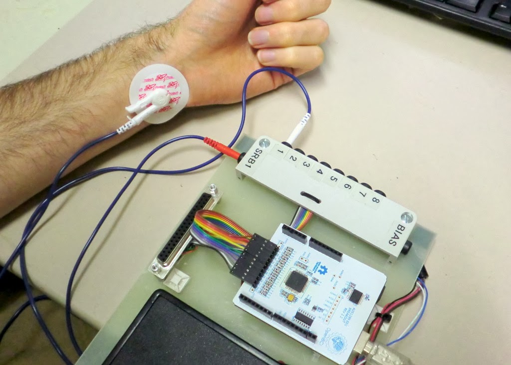
Using OpenBCI to Record my Heart Signals (ECG) from my Left Wrist and Right Wrist (my right wrist not shown because it is holding the camera!)

ECG Overview

EEG is the measurement of the electrical signals generated by your brain.  By contrast, ECG is the measurement of the electrical signals generated by your heart.  When the heart contracts, it generates a relatively strong electrical gradient in your body.  With electrodes on your skin, you can measure the difference in potential (ie, voltage) across your body caused by your heart.  That's what the ECG records.

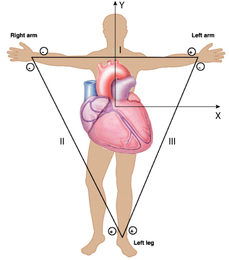
ECG Can Be Measured Across Many Locations.  I'm going to use my two wrists.
Any measurement of electric voltage is a comparison of electrical potential between two different locations in space.  Therefore, to record one's ECG (or EEG), you need to attach at least two electrodes to your body.  Given that ECG signals are so strong, you have lots of choices of where to put your electrodes.  The only requirement is that your two measurement locations are on either side of the heart.  For me, my wrists are a very convenient, so that's where I'm going to attach my electrodes.

Hardware Needed

To measure one's ECG, you need electrodes to attach to your skin, you need wires to connect the electrodes to your electronics, you need some signal acquisition electronics that are appropriate for biosignals, and you need a computer and some software to record and visualize the ECG signals.  I'm going to talk about each of these elements in the sections that follow.

Electrodes:  Electrodes are simply pieces of metal that are electrically connected to your skin.  As long as you make good contact, nearly anything can be used as an electrode...they do not have to be specific to ECG.  If you don't want to get ECG electrodes, you could use EEG electrodes, you could use a piece of copper tape, or you can even use a piece of bare wire (if you can keep it attached to your skin).  But, I want to make this easy for myself, so I'm going to use cheap, disposable ECG electrodes.

I like the disposable ECG electrodes because they are self-adhesive, they come with conductive gel already attached, and they have a nice little button snap for attaching lead wires. They can be purchased from many, many places on-line.  One source is BioPac, where they are $0.38 each.  You can find them even cheaper, if you search around.


To put them on your skin, many websites talk about preparing your skin with an abrasive rub followed by alcohol.  While this is important if you want high-fidelity signals, we don't need this kind of quality.  We're just trying to see if our electronics work.  Therefore, no preparation is necessary.  Simply find a piece of skin without too much hair (for me, that's the inside of my wrists), peel off the paper backing, and stick them to your skin.  Easy!

Self-Adhesive Disposable ECG Electrodes Stuck to my Wrists.
ECG Lead Wires:  With the electrodes on the wrists, you need wires to bring the signals back to your electronics.  Again, there is no magic here.  You can use any wire.  Because I'm making life easy for myself, I bought some ECG lead wires that are made to connect to the button snaps on the ECG electrodes.  There are several different styles of these wires...some with snaps and some with clips.  I happened to get the ones with clips, but it doesn't really matter.  As when buying the electrodes, you can buy lead wires lots of different places.  I don't remember where I got mine.  Some are available from Biopac, or you can just check out Amazon.

The ECG lead wires that I use.  They have nice clips on the ends (picture on right) for attaching to ECG electrodes.  They also have the "touchproof" connectors on the other end for connecting to standard ECG electrodes.  Alternatively, you can use plain wire, if you prefer.
When selecting which lead wires to buy/make, the only trick is in the connector that attaches to the electronics.  Most ECG leads come with these nice little push-plugs that are referred to as "touchproof connectors".  They have this name because the electrical contacts are fully shrouded by plastic and can't be touched.  Note that EEG electrodes often come with the same type of connectors, too, which makes the ECG/EEG transition easy.  While you can always just cut off the connectors and use the raw wire, I like these connectors.  The challenge with the touchproof connectors is that they come in a few different diameters.  So, if you want to use the connectors, it's good to know what diameter connectors are on your wires so that you can buy the correct mating jacks.  My lead wires happened to have 1.5 mm connectors.

Since my EEG electrodes have the same 1.5 mm touchproof plugs as my ECG lead wires, it made sense to me to invest the time and money to buy the mating touchproof jacks.  I bought some 1.5 mm touchproof jacks from PlasticsOne.  I happened to buy the panel-mount version, but PCB mount would also be a good choice.  At over $3 each, these are not cheap.  They are convenient, though.  I mounted the jacks to a scrap piece of plastic and soldered on some wires to go to my electronics.  Easy.


Electronics:  The whole point of this exercise is to use my heart signals as a way of testing my EEG electronics.  So, for me, I'll be using EEG electronics (OpenBCI, OpenEEG, whatever).  But, if you were just doing ECG, ECG signals are generally stronger, which means that the electronics do not need to have such low self-noise.  As a result, ECG electronics tend to be cheaper than EEG electronics.  Regardless, I'm using EEG electronics.  In this case, I'm using OpenBCI.

For my setup, I connect one lead wire to "Input 1" (the "+" input) and one lead wire to the common reference input, "SRB" (the "-" input).  See the picture below.


Computer and Software:  Obviously, any computer will work...you just need one that will connect to your ECG/EEG electronics.  OpenBCI interfaces to the computer via an Arduino Uno.  That part is easy.  The harder part is what software to use on the PC.  You could use the custom displays that we have made for OpenBCI.  Or, following up from my last post, you could use BrainBay, which is an open source biosignal analysis program for Windows.  I recently wrote a software interface for OpenBCI to allow its data to be received and processed by BrainBay.  That's what I'm going to use here.

ECG Results

With the setup that I described above, I started BrainBay, relaxed my wrists (muscle contractions make electricity, too, which can mask the ECG signal), and watched my ECG data scroll by on the BrainBay display.  Some example data is shown below.  It should the ECG signal recorded for four heart beats.  It's always comforting to scientifically confirm that one's heart is beating.

ECG Signal Recorded using OpenBCI and Visualized using BrainBay.
I find the ECG signal itself to be fascinating.  Each component of the waveform corresponds to action in a different part of the heart.  Below, I've excerpted one heart beat from the waveform above and have shown it with annotations.  The little bump (downward in my data above) is the "P-wave", which is the atria contracting to push blood to the ventricles.  The sharp spike is the "R-wave", which is main contraction of the ventricles to push blood out to the body.  The big long bump is the "T-wave", which is the ventricles relaxing and re-polarizing to get ready for the next heart beat.  Note that usually the R-wave is much bigger and that the P- and T-waves are inverted compared to this trace, so I probably just had some wires plugged in backwards.  Still, all the components are there and they look pretty good.

Compared to the challenges in measuring EEG signals from the scalp, I find that ECG is way easier to measure reliably.  That's why I use it as my first test of an EEG system.  If I stick electrodes on my wrists  and don't see a signal like that shown above, I know that something is wrong with the electronics and not my body.  If you find yourself hacking EEG systems for fun, you might want to consider using this technique as well.  Plus, you might learn something about ECG and your heart, which is cool, too!


Follow-Up: In trying my homemade electrodes, I used ECG as my first test.
Follow-Up: I also was able to measure EOG using a similar setup.
Follow-Up: I've now tried to share the data from this post on my github.  Try it!

Saturday, November 2, 2013

BrainBay - EEG Visualization Software

When I got started with EEG, I started with the OpenEEG project and the excellent information that they have available.  That led to me buying the SMT version of the OpenEEG hardware available from Olimex.  Once I got that hardware, it led me to downloading and using BrainBay, which is an open source software for receiving, processing, and visualizing biosignals, especially EEG signals.  While the interface feels a little quirky when you first start using it, it is surprisingly flexible and powerful.  I decided that I wanted to be able to inject data from our OpenBCI EEG system into BrainBay so that I could use its processing and display tools.

Screenshot from BrainBay's Website of One Person's Processing and Visualization Configuration.  The configurations are completely user defined, which is powerful...and confusing to a new person.

>>> Getting Data into BrainBay

By default, BrainBay can be configured to receive data streamed from a few different EEG systems.  It seems that most people probably use the OpenEEG hardware (such as the Olimex unit linked earlier).  The OpenEEG hardware communicates to the PC using a binary data format.  If I want to inject OpenBCI data into BrainBay, the easiest way is to make my OpenBCI system look like an OpenEEG system.  This means that I need to alter my Arduino software (which is what my OpenBCI is connected to) to output the EEG data in the same format as used by OpenEEG.  Easy!

Um, but what is the OpenEEG data transfer format?

Well, the core of the OpenEEG hardware is an AVR processor like the Arduino, so the embedded software running on the OpenEEG hardware should be intelligible to someone with experience in Arduino.  You could download the software, read it (if you were suitably skilled) and figure out the data format.  Given the number of AVR macros employed in that code, however, figuring out what's going on can be challenging for a lot of folks (including myself).

Alternatively, if you look in BrainBay's own Developer Manual and jump to Section 6, it discusses the data format in actual words.  Very nice.  I chose to target the "P2" data format.

You may notice that this format has a couple of limitations relative to the capabilities of OpenBCI.  First, this data format only allows for 6 EEG channels, whereas OpenBCI has 8 channels.  So, we'll lose two EEG channels, which is unfortunate but not horrible.  Second, note that this format only allows for 16-bit EEG values, whereas OpenBCI generates EEG data samples at 24-bit resolution.  So, I'll have to cut 8 bits of resolution, which means that I'll lose some dynamic range.  A 16-bit value still has a lot of dynamic range, so this will probably be OK.

(Super-technical aside:   I'll need to decide whether to truncate the lowest bits (and lose resolution at the lowest signal levels) or to cut the highest bits and lose the ability to handle large DC offsets.  I think that I'll split the difference and cut some from both the high and low sides of my dynamic range.  For the moment, I do this by dividing my 24-bit sample by 32 and cast from my 32-bit data type to a 16-bit data type.  The "divide by 32" step, in effect, drops 5 bits of resolution from the low end of my dynamic range, which means that the casting drops 3 bits of headroom on the high end of my dynamic range.)

>>> Configuring BrainBay for OpenBCI

So, after writing a small extension to my existing Arduino software for translating the OpenBCI data into this new format, I can successfully get my OpenBCI data into BrainBay.  Yay!  There are, however, a couple of small changes to the settings in BrainBay to get the most out of the OpenBCI data.  Specially, in the "EEG Block" used by BrainBay to get data from the EEG hardware, you'll need to alter the "Baud Rate"," Sampling Rate", and "Resolution".  With my current settings in the Arduino software (which might change in the future), here's how I configured the EEG input block in BrainBay:

To Use OpenBCI in BrainBay, select "Modular EEG P2" and then change the Baud Rate to 115200, change the Resolution to 1432 and (not shown) change the Sampling Rate to 250 Hz.
Baud Rate:  OpenEEG defaults to 56000 bps whereas I configured my OpenBCI Arduino software to run at 115200 bps.  If you don't change this value, BrainBay probably will not be able to receive the data from OpenBCI.

Sampling Rate:  OpenEEG runs at 256 Hz.  The sampling rate for OpenBCI has several different settings, but my Arduino software has it running at 250 Hz.  In BrainBay, you should change the value to 250 Hz so that BrainBay shows the graphs with the correct time and frequency scales.

Resolution:  OpenEEG samples have a resolution of 10-bits (ie 1024 counts).  Full-scale is 512 uV (ie, +/- 256 uV).  BrainBay always assumes that full scale is 512 uV and, in this window, it is asking how many counts correspond to 512 uV.  For OpenEEG, you enter 1024 because it spans 512 uV with its 10-bit (ie 1024 count) digitizer.  For OpenBCI, it's a little more complicated.  The correct value (for now) is to enter 1432.

(Second super-technical aside:  I get this value by finding OpenBCI's internal scale factor, which is (2^24) / (4.5 V / 24x Gain) = 89.5 counts / microVolt.  I then cut this down by by 32x bit-reduction divisor discussed earlier, which yields 2.796 counts / microVolt.  Finally, BrainBay expects "full scale" to be 512 uV, so to find out the number of "counts" it takes to represent this value, you take 512 uV * 2.796 counts / microVolt and get 1432 counts.  Viola!)

>>> Example: OpenBCI Data in BrainBay

Once you get all of those settings correct, you can setup a simple data flow in BrainBay and start watching your OpenBCI data flow smoothly and beautifully.  Below is an example of using OpenBCI for ECG (see here for the setup).  You can see the four blocks: (1) the EEG block to receive the data from OpenBCI via serial link, (2) a sharp 60 Hz notch filter to eliminate line noise, (3) a gentle bandpass filter to remove low frequency drift, and (4) an oscilloscope block to graph the data.  Look at how nice and clear my ECG is!

Using BrainBay to Receive Data from OpenBCI and Plot the Results in Real Time.  Awesome!
My favorite part of getting my data into BrainBay is that the filtering and graphs all run in real-time.  There are signal detection blocks that you can insert which can then be connected blocks that play sounds for feedback (or launch video or animation).  It's quite powerful.  Sure, I could write all of this in Matlab (which I did for Maker Faire NYC) or in Processing (which I just completed) or in Python (which we're still working on), but those programs are not as easy to reconfigure quickly as BrainBay.  BrainBay is very nice for that.

>>> Next Steps

The major downside of BrainBay is that it is only on Windows.  In the future, I'm going to look into interfacing OpenBCI with OpenViBE, which is another powerful open source software platform for receiving, processing, and visualizing EEG data.  It looks like it is also primarily aimed at Windows, but it is nice to have another choice in addition BrainBay and in addition to my own Matlab and Processing and Python interfaces.


Follow-Up: Here's a post where I describe how to make ECG measurements.
Follow-Up: Chris (the developer of BrainBay) wrote a BrainBay driver for OpenBCI.  Check it out!