Showing posts with label Electrodes. Show all posts

Friday, April 11, 2014

Impedance of Electrodes on my Head

Following from my previous post on figuring out how to get OpenBCI to measure the electrode-to-skin impedance, I figured that now is the time to actually measure the impedance of real electrodes on my actual skin.  I decided to try two types of electrodes: (1) disposable ECG electrodes and (2) re-usable gold cup EEG electrodes.  Here's the story of what I found...

On the left, I'm trying ECG electrodes.  On the right, I'm trying
gold cup EEG electrodes.  In both cases, I'm looking pretty sharp.

Disposable ECG Electrodes:  First, I decided to try some disposable ECG electrodes.  These are cheap and really easy to use.  They're not very good for using in your hair, but they're great for sticking on your forehead.  For the reference and bias connections, I used an ECG electrode on the mastoid bone behind each of my ears.  The picture below shows the pre-gelled, self-adhesive ECG electrodes that I used along with the clip-type ECG electrode wires (see this post for specific recommendations).

ECG Electrodes and Clip Leads That I Used on my Head

Once I stuck three of these electrodes on my head (forehead and behind each ear), I connected the lead wires to my OpenBCI V1 board using my homemade adapter.

Connecting the ECG Leads to my OpenBCI V1 Board.

After getting all connected, I activated the ADS1299's "Lead Off" excitation signal for the channel that was connected to the ECG electrode on my forehead.  As discussed in my previous post, the excitation signal is a 6 nA AC current source that the ADS1299 toggles at 31.2 Hz.  The flow of current through the electrode creates a voltage that can be measured by OpenBCI just like a normal EEG signal.  I configured my OpenBCI board to digitize the data and send it to the PC.  On the PC, I used the OpenBCI GUI to view the data in real time and to record it for post-test analysis.

A zoomed-in plot of the recorded waveform is shown on the left of the figure below.  As you can see, it has a fairly large amplitude of 508 uVrms.  This corresponds to an impedance of 120 kOhm.  That's really big!  Being surprised by that large value, I swapped the wires around so that I was measuring the electrode that I had been using as my reference (or "-") electrode.  As seen in the waveform above on the right, I got a very similar value.  That's not cool.

Example Waveforms Recorded While Using OpenBCI To Measure the
Electrode-to-Skin Impedance of (Left) the ECG Electrode on my
Forehead and (Right) the ECG Electrode behind my Left Ear.

Zooming out so that you can see more of my recording, the figure below shows about a minute's worth of data.  This is the full recording from which I made the excerpts shown above.  The longer view below shows the story of me recording data for one electrode (up to about t = 119), of how the signal goes away as I unplug and swap the electrode connections (from t = 120 to t = 132), and then how the signal returns once I am connected to the other electrode.  Again, you can see that I measured 120K from one electrode and 116K from the other electrode.

Zoomed-Out View of my Recordings Using the "Lead-Off Detection" Excitation
while Using Disposable ECG electrodes.

Gold Cup EEG Electrodes:  Because I found the impedance of the ECG electrodes to be surprisingly high, I tried using some gold cup EEG electrodes.  The picture below shows the electrodes and the conductive electrode paste that I used.  Like with the ECG electrodes, I put one of these on my forehead, one on the bone behind my left ear for the EEG reference and one one the bone behind my right ear as the EEG bias.

Gold Cup EEG Electrodes and Ten20 Brand EEG Paste

After putting on the electrodes, I activated the "Lead Off" excitation, like before.  Some examples waveforms from the data that I recorded are shown below.  As expected, the waveform shape is the same as seen before, but the amplitude is different, which reflects the fact that the impedance of the electrode-to-skin interface is different.
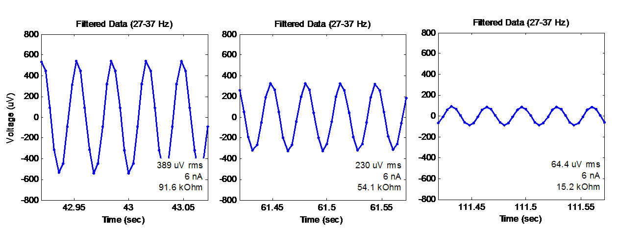
Waveforms Recorded from the Gold Cup Electrodes During the "Lead Off" Excitation.

Notice that the three plots show decreasing amplitude, which means that I was getting better contact and less impedance in each case.  What was happening?

Well, for the first waveform (the one on the left) was shows what I measured when I first attached the electrodes.  It shows an RMS amplitude of 389 uV, which corresponds to an impedance of approximately 92 kOhm.  This was still higher than I wanted, so I fiddled with the electrode and pushed it into my skin to try to make better contact.  That's when I got the middle graph -- 230 uV and 54 kOhm.  Finally, I pulled off the electrode, replaced the conductive paste, and really pressed and twisted the electrode against my skin.  That's when I got the graph on the right -- 64 uV, which corresponds to 15 kOhm.  That is more like the kind of value that I was hoping to see.

Below is a zoomed-out plot of the whole scenario with the gold cup electrode.  Again, this is the full record from which I made the excerpts above.  On the left side of the plot, you can see the 389 uV, 92 kOhm condition that I showed before.  Then, you can see my multiple attempts at re-seating and re-pasting the electrode.  Finally, at the end, I finally got to the 64 uV /  15 kOhm condition.  So, while it does take some effort, it is possible to improve the electrical contact between the electrode and your skin.

Zoomed-Out View of my Recordings Using the "Lead-Off Detection" Excitation
while Using the Gold Cup EEG Electrodes

Why Were the ECG Electrodes So Bad?  This experiment started with the ECG electrodes, which yielded a very high impedance of 120 kOhm.  If I could only use the ECG electrodes, this high impedance value would have prompted me to remove the electrode, to scrub the skin (hard!) with alcohol and a rough pad, and then to attach a new electrode.  Maybe this would have worked to lower the impedance, or maybe not.  If it would not have helped, the problem could be that my ECG electrodes are really old.  If you look really closely at my picture showing the electrodes, you'll see that the ECG packet in the background shows a date of "June 2012".  Yikes!  I have a friend who is developing a hacker-friendly EMG system (go FlexVolt!) who has mentioned to me that he has seen difficulty when using old ECG electrodes.  So, I'm thinking that maybe disposable electrodes have a limited shelf life...and that 2 years is maybe too old.

Next Steps:  With the impedance monitoring working on my OpenBCI board, I'm hoping that it will enable me to make more reliable EEG recordings. Hopefully, getting good low-impedance connections will increase my chances of detecting those low-level signals that have vexed me with their sometimes-I-see-them and sometimes-I-don't behavior.  In particular, I'm thinking about those pesky Mu waves that have been hard for me!  We'll see if this impedance checking can help...

Thanks for reading!

Follow-Up: Want to get the data from this post?  Try downloading it from my github!

Saturday, January 18, 2014

EEG Electrode Adapter - Version 2

As many people are aware, many commercially-available EEG electrodes use an unusual connector called a "touch-proof" connector.  If your EEG system does not use these connectors, you need to either replace the connectors on the electrodes, or you need to make an adapter.  While it is a sensible choice to cut up your electrodes, I prefer to make an adapter.  My previous version of such an adapter worked really well, but it was a bit fragile.  So, I decided to try again.  I also decided to work with a friend of mine who's a little smarter about these kinds of things.  Here's what we came up with.

My Revised EEG Electrode Adapter ("V2") attached to an OpenBCI Board

Problems with the Previous Version:  The picture below shows my previous version of the adapter.  The good part was that the adapter was really small.  I liked that.  The bad part of this adapter (in addition to the fact that I never finished all of the connections) was that it was quite fragile. Specifically, the soldering of the wire to the female connector had no strain relief, which meant that mating the connector always threatened to break the wiring.  Another problem was that I was always confusing which electrode I had plugged into which input on the OpenBCI board.  I really needed to remake the adapter so that it was easier to see which were the "special" connections (SRB, Bias, and 8P) versus all of the "normal" connections (1N-8N).  These are the deficiencies that I focused on in this revision.

My First Attempt at an EEG Electrode Adapter ("V1")
Revised Approach:  With this iteration, my friend and I decided that it would be best if the female touch-proof connectors were mounted to some sort of rigid frame instead of merely being attached to the ends of the wires.  This would give the strain relief that we needed when mating and de-mating the connectors.  To address my other issue -- getting the connections confused -- I decided to use color-coded connectors, instead of just the black connectors in my first build.  Easy.  Ok, let's go!

Parts:  The parts are all the same as in the first build.  The female touch proof connectors are P/N 36145 from Plastics One.  The ribbon cable is just a set of female-female jumper wires from Adafruit (P/N 266).  This time, we also used a piece of scrap plastic channel that we had lying around, probably originally from McMaster-Carr.  And, as you'll see, I used a thin scrap piece of plastic sheet and a wide piece of shink tube, both from our generally pile of "goodies for a future project".  None of these pieces (except for the female touch-proof connectors) are particularly critical, so use what you have.

Assembly:  My buddy who came up with the idea of using the plastic U-channel as a mounting plate did all of the of the assembly.  He started with drilling a bunch of holes in the U-channel into which he pressed in the female connectors.

Touch-Proof Connectors Mated to the U-Channel -- For Strength!

He then took the purchased wires, pulled off (as a group) the number of wires that we needed and cut the existing connectors off one end.

Inexpensive Jumper Wires Used for My Wire Bundle

To keep the individual wires from splitting themselves off the ribbon, he reinforced the ribbon with a flat piece of plastic and a big piece of shrink tube.  Here's him preparing the items.  The red thing is the big shrink tube and the yellow-ish thing is the scrap bit of flat plastic that he'll use for the reinforcement.


Preparing the Shrink Tube (Red) and Scrap Plastic (Yellow)
to Reinforce the Wire Bundle

With the wire bundle prepared, he soldered the individual wires to the back of the touch proof connectors.  He used some normal size shrink tube to protect the individual solder joints on the back of the connectors.  Very nice.

Connecting the Individual Wires to the Back of the
Touch-Proof Connectors.

And that's all there is to it.  A picture of the completed unit is below.  You can also see it attached to an OpenBCI board at the top.  In the picture below, you can see how reinforcing the ribbon cable was an important feature for keeping the wire bundle from falling apart.

The Finished Adapter.

Pin-Out:  For anyone wondering why I used the unusual color scheme for the connectors, the idea is to clearly indicate that some of the electrodes have different functions.  So, if you use this adapter to connect to the OpenBCI V2 board as shown in the zoom'd picture below, or like the one at the top of this post, the order of the connections is this, from left to right:

   Red: Bias  (aka. driven ground)
   Blue: 8N  (the regular input for channel 8)
   Red: 8P  (the reference input for channel 8, if selected in software)
   Blue: 
       7N  (the regular input for channel 7)
       ...
       1N  (the regular input for channel 1)
   Red: SRB2  (the reference input for all channels)

Further Revisions:  After working with this revised piece for a bit, I found that there is still room for improvement.  For example, in connecting the adapter to the OpenBCI board, it is important to connect the wires in the right order.  The right order is shown below.  At first, I thought it was a good idea that I kept the individual female pin connectors on each wire of the adapter.  I thought that I'd like the freedom and fllexibility that this might provide.  I was wrong.  I should have swapped out the individual female pin connectors for a ganged female connector that would have kept them all in the right order all of the time.  I was wrong.  (So, to the EEG hacker that I'm handing this adapter off to, sorry for the annoyance!).

The Correct Order for the Individual Wires.

So that's the story of the hacking of this electrode adapter.  The real solution, of course, would be to have the connectors on the electrodes and on the EEG system (OpenBCI, in my case) be the same.   The easiest thing would be to put female touch proof connectors on the OpenBCI board.  But, the PCB-mount version are almost $2/each, even in quantity!  This is completely incompatible with the price of the OpenBCI board.  So, the next option would be to buy electrodes with a connector system that we could afford.  That would be a really nice solution to this problem of making kludge-y adapters.

Tuesday, November 12, 2013

Making an EEG Electrode Adapter

My earlier post on making my own EEG electrodes was surprisingly popular.  Thanks, all!  But, for some folks, it might just be easier to purchase EEG electrodes off the shelf.  If you buy your electrodes, they're likely to come with connectors on the ends.  In order to use these electrodes with an OpenBCI board, you'll need to either cut the connectors off, or you'll need to make an adapter cable.  Since I tend to play with a variety of electrodes (both EEG and ECG) and since many types of electrodes use this same connector, I thought that it would be good to make an adapter.  This post is about how I made my adapter cable.  Here's what it looks like when I was done.


Parts

To make the adapter cable, you need the connectors that mate to the EEG electrode, you need some wires, and you need some connectors that mate to the OpenBCI board.

The OpenBCI board simply uses pin headers with a 0.1" spacing.  Therefore, for "connectors", you can use any of the inexpensive jumper wires that are used throughout the hobby world for connecting to Arduino.  For this adapter cable, you need female pin headers.  Adafruit sells a fine pack of 40 female/female jumper wires (P/N 266) for $6.95.  The 40 wires come with the connectors already attached.  The wires also come attached to each other as a ribbon cable, which is very convenient for keeping the cables in order.

Female/Female Jumper Wires from Adafruit
For the EEG electrodes, they usually use "touchproof" connectors.  This are simple singe-conductor connectors where the metal part is completely shrouded in plastic.  They are fairly standardized, though the diameter of the connection can vary between 1mm and 2mm.  All of my electrodes are 1.5mm.  The jacks that mate to these electrodes can be purchased from Plastics One.  Specially, I chose to buy the panel mount, front-loaded, threaded connectors (P/N 36145) shown in the pictures below.  When bought in small numbers, they're $3.14 each.  That's pricey!

Jacks for Touchproof Connectors.  From Plastics One.
Assembly

The OpenBCI board has 11 connections that I might want to use.  So, I took the ribbon of 40 jumper wires and peeled off a single strip that contained 11 wires.  I then cut it in half to that one end had the female pin headers and the other end was just wire.


Then, I peeled apart the ends of the wire and stripped the ends.  As I prepared to solder on the touchproof jack, I slipped a piece of shrink tube over the end of the wire so that I could make it look nice when I was done.  I'm proud of myself for remembering to do the shrink tube.  I nearly always forget.  Not this time!

Preparing to solder the first jack.

After I soldered it on, I pulled the shrink tube up over the joint, applied some heat, and got a nice looking connection.

First jack is attached.  Nice use of shrink tube!
I then repeated the process for all the other wires that I was going to use.  Here's a picture of me soldering on the second jack.

Preparing to solder the second jack.
Completion

For my immediate testing, I did not need all 11 connections...I only needed four.  So, I only soldered on four jacks.  You can see my "completed" adapter cable assembly below.

My adapter cable with 4 connections.  I'll add the others when I need them.
Note that I added a piece of electrical tape around the ribbon cable to help keep it together.  I had overly separated one of the individual wires and it was threatening to come loose.  I little electrical tape saved the day!  And it makes it look fancy.

Using It

As you can tell by the photo at the top of this post, the adapter cable works great for interfacing OpenBCI to off-the-shelf electrodes.  I've used it with my EEG electrodes for follow-on measurements of my Mu-waves and with my ECG electrodes for checking my heart signals.  It's a great adapter cable to have in my EEG Hacker toolbox!


Wednesday, November 6, 2013

Waveforms from Homemade Electrodes

As follow-up to my surprisingly popular post on my homemade electrodes, ERPOLOGY asked to see the EEG traces.  Well, since making graphs is one of my most favorite things to do (NERD ALERT!), I'm happy to oblige.

First, as a reminder of what I did, I built some EEG electrodes out of really cheap materials.  To see how well they worked, I stuck them to my head using Ten20 conductive paste in locations approximating Cz (top of head) and C3 (side of head).  The spectrogram above shows the data that I recorded.  As you can see, the test contains several test conditions:
  1. Closed Eyes (to see Alpha Waves)
  2. Open Eyes and Relaxed (to see Mu Waves)
  3. Open Eyes While Moving Hand (to suppress my Mu Waves)
Time-Domain Plots

OK, now let's make the new plots.  First, I've chosen short excerpts from each of the three periods.  I've plotted them below.  Note that these plots are zoomed way in so that you can count the period of the Alpha waves and of the Mu waves.

First, below, I show a trace from when my eyes were closed and I was generating Alpha Waves due to my Posterior Dominant Rhythm (PDR).  Remember, my electrodes were not on the back of my head -- they were on the side of my head.  So the PDR Alpha waves are not as pure looking as you might expect.  If you count the peaks, though, you'll see that there are about 9-10 cycles per second (ie, 9-10 Hz), which is what we saw in the spectrogram at the top.


Next, below, I show a trace from when my eyes were open and I was trying very hard to be relaxed (an oxymoron).  I was successful in generating some Mu waves.  They're shown below.  If you could the peaks, you'll get 10-12 waves per second (depending on how you count).  Based on the spectrogram, the frequency of my Mu waves is a little bit higher than my PDR Alpha waves.  This is probably confirmed by the peak-counting in the plot below.


The last time-domain plot, below, is for when I open and close my hand.  This should suppress my Mu waves.  In the spectrogram, they do appear to be absent.  In the plot below, they appear to be absent as well.  Good.


Frequency-Domain Plot

Before we finish, let's go back to the frequency domain...but let's plot a regular spectrum and not a spectrogram.  While the spectrogram is great for getting a sense of what is happening throughout the test, it is not the best tool for being quantitative.  Sometimes a simple spectrum plot is better.  

For the spectrum plot below, I took a long sample of each activity (10s of seconds, several thousand data points), I performed a series of 512-point FFTs and I averaged the FFT results together to get a nice, smooth spectrum for each condition.  By plotting the averaged spectrum for each condition all on the same graph, I can quantify the differences between the three conditions.  Here are the results:


As you can see, the Alpha waves were definitely at a lower frequency (9.3-9.8 Hz using my data reading cursor) than my Mu waves (11.7 Hz).  As I mentioned during the discussion of the time-domain plots, the spectrogram showed this fairly well.  But, a basic spectrum plot like this one makes it much easier to see and quantify the difference between the two.

Also, this graph implies that the Mu waves were about half the amplitude of the Alpha waves.  While it is true that Alpha are clearer in the spectrogram, which suggests that the Alpha were stronger, the primary reason that the Alpha were clearer is because I was able to sustain the Alpha waves more steadily than the Mu waves.  Detailed examination of the data shows that my Mu waves came and went every few seconds.  Therefore, in the averaged FFT plot, the apparent amplitude of the Mu waves will appear to be smaller simply because it includes all those short periods where the Mu waves temporarily went away.  That's a risk with using a heavily-averaged spectrum plot.  You gotta know your tool.

Finally, this spectrum plot nicely shows how clenching my hand (the red trace) suppresses the Mu waves completely.  Again, that was clear in the spectrogram, but this plot shows it very nicely as well.

Implications

With this extra detailed view of the data, you can start to see how you could design a signal processing chain to detect Mu waves.  Looking at the frequency plot, it is clear that you would need a really tight filter...maybe about 1 Hz wide.  For me, the filter would need to be centered on 11.7 Hz.  You might have your own special frequency.  Finally, because this plot shows that the energy in my PDR Alpha overlap with my Mu, you might want to sense the frequencies on either side of your Mu waves.  If there is energy on either side of Mu, then it's likely that the energy inside your Mu frequency band is from something else...such as PDR Alpha.

Without a graph like this, designing the signal processing would be much harder.  With this graph, I get all sorts of ideas.  This is why I like graphs so much...they can give quick insight into complex data.

If you've made it this far...thanks for reading!  You're awesome!

Follow-Up: Want to see my data from this experiment?  Check out my github!

Tuesday, November 5, 2013

Homemade Passive Electrodes

After the challenge of getting oneself some decent EEG electronics, the next hardest part is getting some decent EEG electrodes.  Sure, there are lots out there that can be bought, but some folks have no interest in paying $8-$20 per electrode (plus shipping) because they know that they need to buy 6-10 of these electrodes and, well, that becomes a lot of money.  So, I decided to try to build my own homemade EEG electrodes.  Here's my story...(and for you impatient folks...yes, there's a fairly happy ending)

Wearing my homemade passive EEG electrodes.
(Beware of cheap cameras and flourescent lights)

The Idea: Use Cheap Bits from the Hardware Drawer

When I look at passive EEG electrodes, I just see a piece of flat metal with a wire attached.  Sure, I see the use of fancy metals (gold, silver / silver-chloride), but is that really necessary?  For EEG research or EEG medicine, the quality and repeatability provided by the fancy metals is necessary.  For EEG Hacking?  I'm not so sure.  So, if an electrode is just a piece of flat metal with a wire attached, it seems like I should be able to build one myself.

I started by searching through my hardware drawer to find a suitable piece of metal that is small and flat.  I found some lock washers with a solder tab (see picture below-left).  It is a very basic and inexpensive component.  I'm pretty sure that mine are from Mouser and cost $0.24 each.  You can probably get them cheaper.


I then grabbed a piece of wire, stripped the end, and inserted it into the tab on the washer.  Looks like it'll do nicely (see picture above-right).  To soldered the wire to washer, I simply placed it in my plastic-gripped vice and applied heat and solder (pics below).  If you don't have a vice, a traditional "3rd hand" soldering fixture would have worked fine, too.  This is not fancy work that we're doing here.


Once the wire was soldered to the washer, I realized that I should have added a piece of shrink tube over the wire to cover the solder joint.  But, once it was soldered together, it was too late to add the shrink tube (the other end of my wire already had a connector on it).  Dang!  When I made a second electrode, I remembered to add the shrink tube on that one.  As you can see below, the black shrink tube makes the second electrode look much nicer than the first one.

My First and Second Homemade Passive Electrodes.  On the second one, I remembered to add a piece of shrink tube to cover the solder joint.  It looks much better.
With the working end of the electrode complete, I could consider the other end of the wire...the end where normally on would add a connector for plugging into the EEG electronics.  Since I stole my wire from an old ECG lead wire, I have the "touchproof" connectors on the end of my electrodes.  But, you don't need anything that fancy if you want to spend less money.

The least expensive approach for "connectors" would be to solder on a male or female pin header, which are only about $0.04 per connection.  This kind of connection is perfect for connecting to OpenBCI, which is built around traditional 0.1" spaced pin headers.  So, if you put the mating gender of pin header on your homemade electrodes, they could plug right into the OpenBCI board.  Great!  Alternatively, if you use OpenEEG, you will want to terminate your electrode's wire with a 3.5 mm stereo phono plug.   That is what the OpenEEG is built around.  These pieces about $0.50 each.

So, overall, I estimate that cost of each one of these electrodes is: $0.24 for the washer, about $0.36 for a meter of stranded wire (it's more flexible than solid wire), and $0.50 for a 3.5mm connector.  That's $1.10 in parts, which is a nice reduction compared to commercially available electrodes linked at the top of this post.

But do my homemade electrodes work?

Homemade Electrodes for ECG

As discussed in my previous post, I always like to start my testing by doing ECG measurements.  Because the heart signals are so strong, it is an easy way to confirm that your EEG system (and EEG electrodes) are working to some degree.  So, I got out my tube of Ten20 conductive paste and stuck my electrode to my wrist.  I attached one electrode to my left wrist and the other electrode to my right wrist.

Attaching my homemade electrodes to my wrists to measure my ECG.
The shiny stuff on my skin is Ten20 conductive paste

 How well did they stick?  Well, not nearly as well as the self-adhesive disposable ECG electrodes.  But, the surface area on those sticky ECG electrodes is HUGE, so of course my little electrodes won't stick as well.  Given how small my electrodes were, though, I think that they adhered adequately well.  I think that the big hole in the middle of the washer is not helpful.  If it were solid, I think that these electrodes would stick better.  I'll remember that when I go to make my next set of homemade electrodes.

Once I got the electrodes attached to my wrists, I connected plugged them into my OpenBCI board and had the Arduino pipe the data to my computer, as usual.  Example ECG data from these electrodes is shown below.  I'm showing 6 heart beats.  As you can see, the sharp R-waves and the broad T-waves are both very clear.  The amplitude of the ECG is similar to what I showed in my post yesterday when I used real ECG electrodes.  So, while my signal trace does look a bit noisier than yesterday, I'd say that this is a successful test!

My ECG As Recorded through OpenBCI Using my Homemade Electrodes

Homemade Electrodes for EEG

Since I was successful with the ECG, I made the next step and used my homemade electrodes to acquire some EEG signals.  I am still pretty fixated on my Mu waves, so I decided to use my electrodes to see if I could pick up my Mu waves.

Following a simplified version of my previous procedure, I put one electrode near the top of my head near Cz and one the left side of my head near C3.  As you can see in the photo, it is very tricky to accurately place electrodes on one's own head.  In retrospect, it looks like the one on the top of my head was a bit too far forward for Cz and the one on the side of my head was a bit too far back and a bit too low for C3.  Regardless, they should be good enough to record *something*, so let's see what I got.


Placing my homemade electrodes near
Cz (top of head) and near C3 (side of head).

Using my OpenBCI electronics, I started recording data from my brain.  I spent some time with my eyes closed to generate Alpha waves (Posterior Dominant Rhythm), I spent some time with my eyes open and my right arm and hand relaxed (to hopefully generate Mu waves), and I spent some time with my eyes open and my right hand clenching and un-clenching.  The results are plotted below as a spectrogram.  Unfortunately, it is not very clear where the boundaries were between these different activities, so it is not clear what we *should* be seeing.  We do clearly see the Alpha waves caused by my eyes being closed.  In the middle of the plot, we might also see some Mu waves, but they are very weak.  I would say that these results are fine for Alpha and bad for Mu.


To try to get better results, I moved the homemade electrode that was on the side of my head.  I moved it a little higher to be closer to where C3 is supposed to be.  Then, I repeated my recordings.  This time, I pressed a button on my computer to mark the boundary between each activities to make my post-test analysis easier.  It turns out that the simple act of pressing the button caused my EEG wires to jiggle, which shows up as artifacts within the data.  It makes it clear when I shifted my activity.  See the results below.


As before, the Alpha waves are quite clear.  This time, though, I do think that I see Mu waves during those periods when my eyes were open and my hand and arm were relaxed.  Then, when I moved my hand, I think that I see that the Mu waves go away.  That's exactly what should happen!  At the end, when I relax again, I think that it is interesting that it takes a while for my Mu waves to come back.  Clearly, I am not very good at relaxing.  That's not much of a surprise to me.  I can be quite excitable...especially when I'm EEG HACKING!

Homemade Electrodes Seem to be Good!

So, with this second test, I'm quite pleased with my homemade electrodes.  The signals that I recorded were pretty good.  There was a lot of 60 Hz noise (not shown in these graphs) but that could be due to me not using the traditional 3rd electrode connection (variously named the "bias" or "driven ground" or "driven right leg") for these recordings.  I also felt that these electrodes did not stick to my head as securely as the gold electrodes that I used previously.  I think that the stickiness can be improved by using a piece of metal with more surface area...maybe a regular flat washer instead of the skinny lock washer.  Still, for about a dollar per electrode, I think that the results are pretty darned good.  I'm pleased.

How about you...have you made your own electrodes before?  How did you do it?  Did they work?


Follow-Up: More graphs and discussion of the data is in this post
Follow-Up: Want to see my data from this experiment?  Check out my github!