If you have never recorded your own ECG, here I'm going to give a photo tour of how I do it. I happen to be using the OpenBCI system, but you can do the same thing with nearly any EEG system. For example, when I first got my OpenEEG board from Olimex, I tested with ECG. It worked just fine.
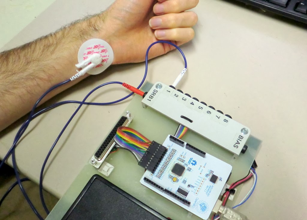 |
| Using OpenBCI to Record my Heart Signals (ECG) from my Left Wrist and Right Wrist (my right wrist not shown because it is holding the camera!) |
ECG Overview
EEG is the measurement of the electrical signals generated by your brain. By contrast, ECG is the measurement of the electrical signals generated by your heart. When the heart contracts, it generates a relatively strong electrical gradient in your body. With electrodes on your skin, you can measure the difference in potential (ie, voltage) across your body caused by your heart. That's what the ECG records.
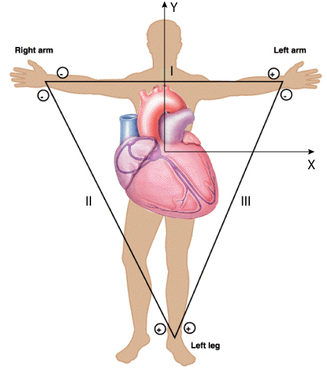 |
| ECG Can Be Measured Across Many Locations. I'm going to use my two wrists. |
Hardware Needed
To measure one's ECG, you need electrodes to attach to your skin, you need wires to connect the electrodes to your electronics, you need some signal acquisition electronics that are appropriate for biosignals, and you need a computer and some software to record and visualize the ECG signals. I'm going to talk about each of these elements in the sections that follow.
Electrodes: Electrodes are simply pieces of metal that are electrically connected to your skin. As long as you make good contact, nearly anything can be used as an electrode...they do not have to be specific to ECG. If you don't want to get ECG electrodes, you could use EEG electrodes, you could use a piece of copper tape, or you can even use a piece of bare wire (if you can keep it attached to your skin). But, I want to make this easy for myself, so I'm going to use cheap, disposable ECG electrodes.
I like the disposable ECG electrodes because they are self-adhesive, they come with conductive gel already attached, and they have a nice little button snap for attaching lead wires. They can be purchased from many, many places on-line. One source is BioPac, where they are $0.38 each. You can find them even cheaper, if you search around.
 |
 |
| Self-Adhesive Disposable ECG Electrodes Stuck to my Wrists. |
 |
| The ECG lead wires that I use. They have nice clips on the ends (picture on right) for attaching to ECG electrodes. They also have the "touchproof" connectors on the other end for connecting to standard ECG electrodes. Alternatively, you can use plain wire, if you prefer. |
Since my EEG electrodes have the same 1.5 mm touchproof plugs as my ECG lead wires, it made sense to me to invest the time and money to buy the mating touchproof jacks. I bought some 1.5 mm touchproof jacks from PlasticsOne. I happened to buy the panel-mount version, but PCB mount would also be a good choice. At over $3 each, these are not cheap. They are convenient, though. I mounted the jacks to a scrap piece of plastic and soldered on some wires to go to my electronics. Easy.

Electronics: The whole point of this exercise is to use my heart signals as a way of testing my EEG electronics. So, for me, I'll be using EEG electronics (OpenBCI, OpenEEG, whatever). But, if you were just doing ECG, ECG signals are generally stronger, which means that the electronics do not need to have such low self-noise. As a result, ECG electronics tend to be cheaper than EEG electronics. Regardless, I'm using EEG electronics. In this case, I'm using OpenBCI.
For my setup, I connect one lead wire to "Input 1" (the "+" input) and one lead wire to the common reference input, "SRB" (the "-" input). See the picture below.

Computer and Software: Obviously, any computer will work...you just need one that will connect to your ECG/EEG electronics. OpenBCI interfaces to the computer via an Arduino Uno. That part is easy. The harder part is what software to use on the PC. You could use the custom displays that we have made for OpenBCI. Or, following up from my last post, you could use BrainBay, which is an open source biosignal analysis program for Windows. I recently wrote a software interface for OpenBCI to allow its data to be received and processed by BrainBay. That's what I'm going to use here.
ECG Results
With the setup that I described above, I started BrainBay, relaxed my wrists (muscle contractions make electricity, too, which can mask the ECG signal), and watched my ECG data scroll by on the BrainBay display. Some example data is shown below. It should the ECG signal recorded for four heart beats. It's always comforting to scientifically confirm that one's heart is beating.
 |
| ECG Signal Recorded using OpenBCI and Visualized using BrainBay. |

Follow-Up: In trying my homemade electrodes, I used ECG as my first test.
Follow-Up: I also was able to measure EOG using a similar setup.
Follow-Up: I've now tried to share the data from this post on my github. Try it!
Nice write up Chip!
ReplyDeleteI'm following a similar path: testing ECG signal with my system (ADS1299 EVM) before touching EEG. I'm lucky to have ECG signal simulator in my lab :)
Beside that, are you missing any posts? You jump from EEG hacking begin and then boom... OpenBCI.
I'm interested to know about your journey with OpenBCI. My lab (me a a lab mate) is trying to build an EEG acquisition system with the ADS1299. I'm scratching my head everyday. My background is EE and I have never done anything in Biomedical Engineering.
It all started with me founding an announcement that DARPA was offering a little money to develop a low-cost EEG system to enable "citizen science" by the common man. I said, "Hey, I like citizen science. I'm a common man. I like electronics (and I do some professionally). Let's make it work!".
DeleteTrue, I didn't know much about EEG specifically, but I did know a little bit about electrophysiologic measurements in general. I also knew of this guy named Joel who did this PulseSensor thing...a super-low cost pulse sensor for hackers. So, I called him up, we made a plan, we won the DARPA funding (now long-past) and he/we made OpenBCI. Joel just achieved his KickStarter, so he'll be carrying it forward. It's an exciting story.
Back to the narrow issue of this EEG Hacker blog...it's not specifically about OpenBCI...it's about me exploring EEG to see what it takes to make something cool happen. Of course, once we got OpenBCI to work, most posts involve OpenBCI. It is a pretty hacker-friendly little system for doing electrophysiologic measurements...though I might be a bit biased ;)
Typo Correction: in the first sentence, replace "...with me founding an announcement..." to "...with me *finding* an announcement...".
DeleteWow, winning a DARPA fund, it's amazing! Your OpenBCI will definately open the door to electrophysiologic measurements for common man. It's great that the KickStarter campaign achieved the goal. It will make the OpenBCI more accessible and build a great community.
ReplyDeleteDon't worry about the topic of your posts. I'm enjoy reading them all. Those EEG related post are great! It's just that I'm struggling with bringing the ADS1299 up so I'm interested in your journey at the beginning. It would be great if you can share it or pointing me somewhere where I can find it. I'm looking for some guidance.
Thanks for sharing!
If you bought the TI ADS1299 Dev Kit, and are trying to use the software that came with the Dev Kit, I feel for your pain. I found it very difficult to do anything beyond just getting a few-seconds of data. I found that the software was quite cumbersome.
DeleteThe Dev Kit is two pieces...a 1299 daughter card attached to a generic TI carrier board (the carrier board has the microcontroller). Perhaps, if had detached the daughter card and tried to attach it to an Arduino or something, it would have been more useful. I never tried.
Joel did all the heavy lifting on getting 1299 working on our OpenBCI board, including the lowest-level software to set the registers correctly. So, you might check out the OpenBCI schematic and the base 1299 Arduino library. All that info is linked on the OpenBCI "Technology" page. Also, check out the forum...there's a discussion of other folks doing their own breakout boards...so you might learn something there, too.
Here's the Technology page: http://www.openbci.com/technology-update/
DeleteHere's the forum topic that I was refering to: http://www.openbci.com/forums/topic/check-out-my-hardware/
My lab bought it. It's my only way to test the 1299 capabilities anyway. I'm not confident to build my board yet but soon.
DeleteYes, I plan to use the Launchpad or Arduino to collect the data from it.
Oh the forum is a great resource. It links me to the Building and Crashing blog where the author posted some design consideration, justification...
Thanks for you help Chip!
Can't wait to hear how it works out for you!
DeleteGreat posting,
ReplyDeleteI have a question. Did you try just getting signal from either wrist?
I am wondering if you can still peak P or T wave
Hi!
DeleteI'm not sure that I understand your question. The recordings that I show above use an electrode on each wrist. The system then records the voltage difference between the two electrodes. So, the signal you see in my plots is the voltage difference between my two wrists.
I could swap the electrodes (well, the electrode wires) going to my two wrists, but that would just invert the signal. Otherwise, it would be identical.
Does that answer what you were asking? Sorry I'm confused...
Thanks for reading!
Chip
Hi, thanks for your response,
ReplyDeleteWhat I meant was "does the single pairing give you the same look as the differential ECG shown here?" To measure the ECG, I know its better to have at least two electrodes doing differential schemes. I am just curious about what one electrode give you on the wrist.
Thank you,
Ben
Hi Ben, I might still be misunderstanding your question...but you can't measure the ECG on just one wrist. ECG is a voltage measurement and voltage measurements are an evaluation of the electrical potential between two points.
DeleteIn a regular electrical circuit, it is common to measure the voltage relative to the circuit's ground. The ground becomes your reference for the voltage measurements.
Your body has no "ground", so you pick a spot and declare it to be your reference. In the pictures above, the red wire (my right wrist) is plugged into "SRB", so it is my reference for all my voltage measurements. In this case, I'm only doing one measurement (ie, my left wrist), so it's a basic normal regular voltage measurement between my wrists. If I disconnect one of my wrists, I get no valid reading -- it just becomes all crazy and noisy with no ECG signal in there.
Perhaps you're asking about what one wrist looks like when you connect it to somewhere else on the body that is NOT the wrist. That's a good question. The answer depends upon where you attach the reference electrode (the red wire). It is common to put it on the leg, but you could try putting it anywhere. And you'll get quite different signals...though they will always have some kind of sharp pulse once per heartbeat. The main difference will be the amplitude of the signal and whether the signal pulses upward or pulses downward.
Hope I answered your question!
Chip
Hi Ben and Chip,
DeleteI think Ben is asking how can you measure ECG with only two electrodes compare to a "normal" ECG setup with 3 electrodes.
I agree with Chip that we need only two electrodes to measure the voltage between two hands. But in fact ( at least from my recording and some of my friends with their ECG recording circuits), differential signals from 2 hands only are very noisy. An additional electrode which connects to the right leg significantly improve the signal quality. Why? I'm not quite sure...
I present my measuring data here:
http://eegexplore.blogspot.com/2014/05/collecting-ecg-signal-with-ti-ads1299.html
um curious about ur article
ReplyDeletehttp://eeghacker.blogspot.com/2013/11/measuring-eog-with-my-eeg-setup.html
Can i have ur EOG sample signal and matlab program...
I'm interested in creating a eog signal filter using FPGA (HDL) but i dont have a sample data... and i like to have matlab program too...
Thank you carry on your good work
email:viraj.uom@gmail.com
I just tried posting my data to my github. Hopefully, it'll work for you:
Deletehttps://github.com/chipaudette/EEGHacker/tree/master/Data/2013-11-08%20EOG
BrainBay doesn't know how to read .mat files. Is this a Matlab project?
DeleteI'm trying to get filters set up in Brainbay just like the above ECG . But I'm lacking the values used and am having serious software stability issues.
I'm not interested in data. I am connected to the device and am seeing data. I just need to filter it.
Hello :)
ReplyDeleteThis article is very interesting.
I have an Olimex EEG SMT with 4 active electrodes and a passive one, how can I use it as an ECG device as you did here?
Thanks!
Eeg Hacker: Collecting Ecg With My Eeg Setup >>>>> Download Now
ReplyDelete>>>>> Download Full
Eeg Hacker: Collecting Ecg With My Eeg Setup >>>>> Download LINK
>>>>> Download Now
Eeg Hacker: Collecting Ecg With My Eeg Setup >>>>> Download Full
>>>>> Download LINK
Getting an ECG test in Delhi is now easier than ever! Whether for routine checkups or specific concerns, ensure your heart's health with a reliable ECG test. Delhi offers numerous top-notch facilities with expert professionals. Don't wait until it's too late—schedule your ECG test today and take a proactive step towards a healthier heart.
ReplyDelete