Monday, November 4, 2013

Collecting ECG with my EEG setup

When playing with a new EEG system (home-built or purchased), it is important to start with signals that are easy to obtain.  By starting with easy signals, you can more readily confirm that your system is working, or you an more readily trouble-shoot it until it is working.  It is for this reason that I always start my EEG hacking by measuring signals from my heart rather than from my brain.  The electrocardiogram (ECG, or EKG) is a far stronger signal with a much easier to see structure than the EEG.  Plus, to measure ECG, you do not need to put sticky, goopy electrodes in your hair.  Yay!

If you have never recorded your own ECG, here I'm going to give a photo tour of how I do it.  I happen to be using the OpenBCI system, but you can do the same thing with nearly any EEG system.  For example, when I first got my OpenEEG board from Olimex, I tested with ECG.  It worked just fine.

Using OpenBCI to Record my Heart Signals (ECG) from my Left Wrist and Right Wrist (my right wrist not shown because it is holding the camera!)

ECG Overview

EEG is the measurement of the electrical signals generated by your brain.  By contrast, ECG is the measurement of the electrical signals generated by your heart.  When the heart contracts, it generates a relatively strong electrical gradient in your body.  With electrodes on your skin, you can measure the difference in potential (ie, voltage) across your body caused by your heart.  That's what the ECG records.

ECG Can Be Measured Across Many Locations.  I'm going to use my two wrists.
Any measurement of electric voltage is a comparison of electrical potential between two different locations in space.  Therefore, to record one's ECG (or EEG), you need to attach at least two electrodes to your body.  Given that ECG signals are so strong, you have lots of choices of where to put your electrodes.  The only requirement is that your two measurement locations are on either side of the heart.  For me, my wrists are a very convenient, so that's where I'm going to attach my electrodes.

Hardware Needed

To measure one's ECG, you need electrodes to attach to your skin, you need wires to connect the electrodes to your electronics, you need some signal acquisition electronics that are appropriate for biosignals, and you need a computer and some software to record and visualize the ECG signals.  I'm going to talk about each of these elements in the sections that follow.

Electrodes:  Electrodes are simply pieces of metal that are electrically connected to your skin.  As long as you make good contact, nearly anything can be used as an electrode...they do not have to be specific to ECG.  If you don't want to get ECG electrodes, you could use EEG electrodes, you could use a piece of copper tape, or you can even use a piece of bare wire (if you can keep it attached to your skin).  But, I want to make this easy for myself, so I'm going to use cheap, disposable ECG electrodes.

I like the disposable ECG electrodes because they are self-adhesive, they come with conductive gel already attached, and they have a nice little button snap for attaching lead wires. They can be purchased from many, many places on-line.  One source is BioPac, where they are $0.38 each.  You can find them even cheaper, if you search around.


To put them on your skin, many websites talk about preparing your skin with an abrasive rub followed by alcohol.  While this is important if you want high-fidelity signals, we don't need this kind of quality.  We're just trying to see if our electronics work.  Therefore, no preparation is necessary.  Simply find a piece of skin without too much hair (for me, that's the inside of my wrists), peel off the paper backing, and stick them to your skin.  Easy!

Self-Adhesive Disposable ECG Electrodes Stuck to my Wrists.
ECG Lead Wires:  With the electrodes on the wrists, you need wires to bring the signals back to your electronics.  Again, there is no magic here.  You can use any wire.  Because I'm making life easy for myself, I bought some ECG lead wires that are made to connect to the button snaps on the ECG electrodes.  There are several different styles of these wires...some with snaps and some with clips.  I happened to get the ones with clips, but it doesn't really matter.  As when buying the electrodes, you can buy lead wires lots of different places.  I don't remember where I got mine.  Some are available from Biopac, or you can just check out Amazon.

The ECG lead wires that I use.  They have nice clips on the ends (picture on right) for attaching to ECG electrodes.  They also have the "touchproof" connectors on the other end for connecting to standard ECG electrodes.  Alternatively, you can use plain wire, if you prefer.
When selecting which lead wires to buy/make, the only trick is in the connector that attaches to the electronics.  Most ECG leads come with these nice little push-plugs that are referred to as "touchproof connectors".  They have this name because the electrical contacts are fully shrouded by plastic and can't be touched.  Note that EEG electrodes often come with the same type of connectors, too, which makes the ECG/EEG transition easy.  While you can always just cut off the connectors and use the raw wire, I like these connectors.  The challenge with the touchproof connectors is that they come in a few different diameters.  So, if you want to use the connectors, it's good to know what diameter connectors are on your wires so that you can buy the correct mating jacks.  My lead wires happened to have 1.5 mm connectors.

Since my EEG electrodes have the same 1.5 mm touchproof plugs as my ECG lead wires, it made sense to me to invest the time and money to buy the mating touchproof jacks.  I bought some 1.5 mm touchproof jacks from PlasticsOne.  I happened to buy the panel-mount version, but PCB mount would also be a good choice.  At over $3 each, these are not cheap.  They are convenient, though.  I mounted the jacks to a scrap piece of plastic and soldered on some wires to go to my electronics.  Easy.


Electronics:  The whole point of this exercise is to use my heart signals as a way of testing my EEG electronics.  So, for me, I'll be using EEG electronics (OpenBCI, OpenEEG, whatever).  But, if you were just doing ECG, ECG signals are generally stronger, which means that the electronics do not need to have such low self-noise.  As a result, ECG electronics tend to be cheaper than EEG electronics.  Regardless, I'm using EEG electronics.  In this case, I'm using OpenBCI.

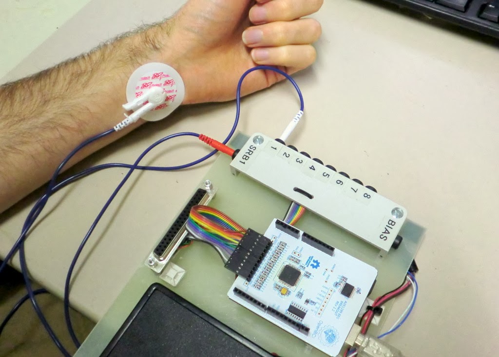
For my setup, I connect one lead wire to "Input 1" (the "+" input) and one lead wire to the common reference input, "SRB" (the "-" input).  See the picture below.


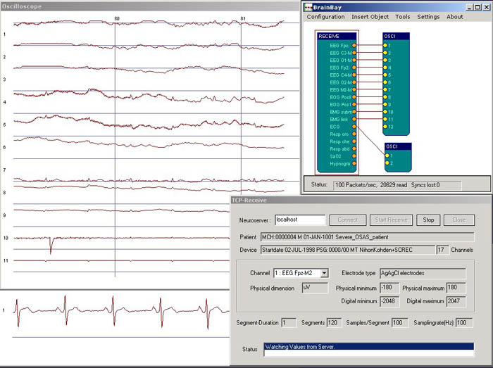
Computer and Software:  Obviously, any computer will work...you just need one that will connect to your ECG/EEG electronics.  OpenBCI interfaces to the computer via an Arduino Uno.  That part is easy.  The harder part is what software to use on the PC.  You could use the custom displays that we have made for OpenBCI.  Or, following up from my last post, you could use BrainBay, which is an open source biosignal analysis program for Windows.  I recently wrote a software interface for OpenBCI to allow its data to be received and processed by BrainBay.  That's what I'm going to use here.

ECG Results

With the setup that I described above, I started BrainBay, relaxed my wrists (muscle contractions make electricity, too, which can mask the ECG signal), and watched my ECG data scroll by on the BrainBay display.  Some example data is shown below.  It should the ECG signal recorded for four heart beats.  It's always comforting to scientifically confirm that one's heart is beating.

ECG Signal Recorded using OpenBCI and Visualized using BrainBay.
I find the ECG signal itself to be fascinating.  Each component of the waveform corresponds to action in a different part of the heart.  Below, I've excerpted one heart beat from the waveform above and have shown it with annotations.  The little bump (downward in my data above) is the "P-wave", which is the atria contracting to push blood to the ventricles.  The sharp spike is the "R-wave", which is main contraction of the ventricles to push blood out to the body.  The big long bump is the "T-wave", which is the ventricles relaxing and re-polarizing to get ready for the next heart beat.  Note that usually the R-wave is much bigger and that the P- and T-waves are inverted compared to this trace, so I probably just had some wires plugged in backwards.  Still, all the components are there and they look pretty good.

Compared to the challenges in measuring EEG signals from the scalp, I find that ECG is way easier to measure reliably.  That's why I use it as my first test of an EEG system.  If I stick electrodes on my wrists  and don't see a signal like that shown above, I know that something is wrong with the electronics and not my body.  If you find yourself hacking EEG systems for fun, you might want to consider using this technique as well.  Plus, you might learn something about ECG and your heart, which is cool, too!


Follow-Up: In trying my homemade electrodes, I used ECG as my first test.
Follow-Up: I also was able to measure EOG using a similar setup.
Follow-Up: I've now tried to share the data from this post on my github.  Try it!

Saturday, November 2, 2013

BrainBay - EEG Visualization Software

When I got started with EEG, I started with the OpenEEG project and the excellent information that they have available.  That led to me buying the SMT version of the OpenEEG hardware available from Olimex.  Once I got that hardware, it led me to downloading and using BrainBay, which is an open source software for receiving, processing, and visualizing biosignals, especially EEG signals.  While the interface feels a little quirky when you first start using it, it is surprisingly flexible and powerful.  I decided that I wanted to be able to inject data from our OpenBCI EEG system into BrainBay so that I could use its processing and display tools.

Screenshot from BrainBay's Website of One Person's Processing and Visualization Configuration.  The configurations are completely user defined, which is powerful...and confusing to a new person.

>>> Getting Data into BrainBay

By default, BrainBay can be configured to receive data streamed from a few different EEG systems.  It seems that most people probably use the OpenEEG hardware (such as the Olimex unit linked earlier).  The OpenEEG hardware communicates to the PC using a binary data format.  If I want to inject OpenBCI data into BrainBay, the easiest way is to make my OpenBCI system look like an OpenEEG system.  This means that I need to alter my Arduino software (which is what my OpenBCI is connected to) to output the EEG data in the same format as used by OpenEEG.  Easy!

Um, but what is the OpenEEG data transfer format?

Well, the core of the OpenEEG hardware is an AVR processor like the Arduino, so the embedded software running on the OpenEEG hardware should be intelligible to someone with experience in Arduino.  You could download the software, read it (if you were suitably skilled) and figure out the data format.  Given the number of AVR macros employed in that code, however, figuring out what's going on can be challenging for a lot of folks (including myself).

Alternatively, if you look in BrainBay's own Developer Manual and jump to Section 6, it discusses the data format in actual words.  Very nice.  I chose to target the "P2" data format.

You may notice that this format has a couple of limitations relative to the capabilities of OpenBCI.  First, this data format only allows for 6 EEG channels, whereas OpenBCI has 8 channels.  So, we'll lose two EEG channels, which is unfortunate but not horrible.  Second, note that this format only allows for 16-bit EEG values, whereas OpenBCI generates EEG data samples at 24-bit resolution.  So, I'll have to cut 8 bits of resolution, which means that I'll lose some dynamic range.  A 16-bit value still has a lot of dynamic range, so this will probably be OK.

(Super-technical aside:   I'll need to decide whether to truncate the lowest bits (and lose resolution at the lowest signal levels) or to cut the highest bits and lose the ability to handle large DC offsets.  I think that I'll split the difference and cut some from both the high and low sides of my dynamic range.  For the moment, I do this by dividing my 24-bit sample by 32 and cast from my 32-bit data type to a 16-bit data type.  The "divide by 32" step, in effect, drops 5 bits of resolution from the low end of my dynamic range, which means that the casting drops 3 bits of headroom on the high end of my dynamic range.)

>>> Configuring BrainBay for OpenBCI

So, after writing a small extension to my existing Arduino software for translating the OpenBCI data into this new format, I can successfully get my OpenBCI data into BrainBay.  Yay!  There are, however, a couple of small changes to the settings in BrainBay to get the most out of the OpenBCI data.  Specially, in the "EEG Block" used by BrainBay to get data from the EEG hardware, you'll need to alter the "Baud Rate"," Sampling Rate", and "Resolution".  With my current settings in the Arduino software (which might change in the future), here's how I configured the EEG input block in BrainBay:

To Use OpenBCI in BrainBay, select "Modular EEG P2" and then change the Baud Rate to 115200, change the Resolution to 1432 and (not shown) change the Sampling Rate to 250 Hz.
Baud Rate:  OpenEEG defaults to 56000 bps whereas I configured my OpenBCI Arduino software to run at 115200 bps.  If you don't change this value, BrainBay probably will not be able to receive the data from OpenBCI.

Sampling Rate:  OpenEEG runs at 256 Hz.  The sampling rate for OpenBCI has several different settings, but my Arduino software has it running at 250 Hz.  In BrainBay, you should change the value to 250 Hz so that BrainBay shows the graphs with the correct time and frequency scales.

Resolution:  OpenEEG samples have a resolution of 10-bits (ie 1024 counts).  Full-scale is 512 uV (ie, +/- 256 uV).  BrainBay always assumes that full scale is 512 uV and, in this window, it is asking how many counts correspond to 512 uV.  For OpenEEG, you enter 1024 because it spans 512 uV with its 10-bit (ie 1024 count) digitizer.  For OpenBCI, it's a little more complicated.  The correct value (for now) is to enter 1432.

(Second super-technical aside:  I get this value by finding OpenBCI's internal scale factor, which is (2^24) / (4.5 V / 24x Gain) = 89.5 counts / microVolt.  I then cut this down by by 32x bit-reduction divisor discussed earlier, which yields 2.796 counts / microVolt.  Finally, BrainBay expects "full scale" to be 512 uV, so to find out the number of "counts" it takes to represent this value, you take 512 uV * 2.796 counts / microVolt and get 1432 counts.  Viola!)

>>> Example: OpenBCI Data in BrainBay

Once you get all of those settings correct, you can setup a simple data flow in BrainBay and start watching your OpenBCI data flow smoothly and beautifully.  Below is an example of using OpenBCI for ECG (see here for the setup).  You can see the four blocks: (1) the EEG block to receive the data from OpenBCI via serial link, (2) a sharp 60 Hz notch filter to eliminate line noise, (3) a gentle bandpass filter to remove low frequency drift, and (4) an oscilloscope block to graph the data.  Look at how nice and clear my ECG is!

Using BrainBay to Receive Data from OpenBCI and Plot the Results in Real Time.  Awesome!
My favorite part of getting my data into BrainBay is that the filtering and graphs all run in real-time.  There are signal detection blocks that you can insert which can then be connected blocks that play sounds for feedback (or launch video or animation).  It's quite powerful.  Sure, I could write all of this in Matlab (which I did for Maker Faire NYC) or in Processing (which I just completed) or in Python (which we're still working on), but those programs are not as easy to reconfigure quickly as BrainBay.  BrainBay is very nice for that.

>>> Next Steps

The major downside of BrainBay is that it is only on Windows.  In the future, I'm going to look into interfacing OpenBCI with OpenViBE, which is another powerful open source software platform for receiving, processing, and visualizing EEG data.  It looks like it is also primarily aimed at Windows, but it is nice to have another choice in addition BrainBay and in addition to my own Matlab and Processing and Python interfaces.


Follow-Up: Here's a post where I describe how to make ECG measurements.
Follow-Up: Chris (the developer of BrainBay) wrote a BrainBay driver for OpenBCI.  Check it out!

Wednesday, October 30, 2013

Conor and his Brain Hat and Android App

One of my collaborators on OpenBCI is Conor.  He's done some really cool EEG hacks.  This one is really sweet:


It uses a Neurosky Mindflex, an Arduino, and a Sparkfun bluetooth module.  It monitors his brainwaves, analyzes the energy content in different frequency bands, and sends the data out over Bluetooth to his Android app.  The Android app that he's using (did he write it or use an existing one?) looks like:


With this app he can log the EEG data along with his mood and activity at the time.  Through post-test analysis he can look for correlations.

Overall, this is a sweet project.  I'm looking forward to stealing...I mean, borrowing...I mean stealing his ideas for my own hacks.

Thanks Conor!


Sparkfun EEG Hacker-in-Residence

I just saw this post from Sparkfun regarding their latest "hacker in residence".  Apparently, Sophi is going to be hacking a Neurosky "Mindwave" EEG headset to create a brainwave interface to other hackable electronics.  Cool!  Here's the quote:

Sophi: I’ll be working with Neurosky’s brainwave headset to create a hardware interface that makers, engineers and educators can use to create projects that trigger on brainwaves. I am very curious about the brainwave headset (it’s called a Mindwave). The Mindwave uses one electrode to measure attention, concentration and eye blinks. I want to see if anything usable can be registered from one sensor intended to get a signal from an object (the brain), that sits inside of a bunch of fluid and then has a skull and hair and skin on top of it.
A couple of years ago I got to ride The Ascent, which uses the Mindwave headset to control the ride. The Rider is strapped into a harness, which is connected to a computer-controlled winch. As the Rider concentrates while wearing the Mindwave, the winch pulls the Rider as high as 30' up towards the ceiling. It was an incredible experience!
I’d like to explore the different applications for this technology, such as using an eye blink to fast-forward your music while running, or wagging a fake tail at ComicCon. Do you have an idea for an application? Put it in the comments!

My favorite part is that this is exactly the kind of stuff that we're looking to enable with our OpenBCI device. I'm always happy when I find folks out there like me who are into brainwaves and into mind-control over their hacks.  Good luck Sophi!

Tuesday, October 22, 2013

Finding My Mu Waves

I'm trying to control things with my brain.  As discussed in my previous post, I think that Mu waves are the best approach that I know about right now.  I tried to get my Mu waves before, but failed.  Now I'm trying again.  This time, I've done a little more learning, so I think that I know how to do it better.  Let's go!

Listening to My Brain
Approach:  The idea with a Mu wave brain-computer interface (BCI) is that I'll use my EEG system to listen to my brain waves.  Mu waves are simple but strong signals in the Alpha band that appear in the sensorimotor (SM) cortex when you relax parts of your body.  The Mu waves go away when you move (or *think* about moving!) those parts of your body.  Supposedly, different regions of the SM cortex correspond to different portions of your body.  So, with careful use of EEG, I might be able to separate thoughts of moving my legs from thoughts of moving my arms.  Seeing other folks do this on the web, this is pretty exciting stuff.

Goal:  My goal today is not to make a full Mu wave BCI.  That's too big a leap.  Today, I just want to see if I can pick up my Mu waves.

Equipment: To do this test, I need some EEG electrodes and an EEG system:

  • For the EEG electrodes, I'm using re-usable gold-plated cup electrodes from Biopac (EL160, see pic below).  This style of electrode is often used in hospitals and in research settings.  I'm using this style of electrode because I can easily slip them within my hair and stick them to the skin.  To use the electrodes, you need some electrode paste, which is both conductive and sticky.  I used Ten20 paste, also available from Biopac.  Just swab some paste into the electrode cup and stick it firmly onto your scalp, with as little hair as possible between the skin and the electrode.

Re-Usable Gold-Plated Electrodes from Biopac
  • For the EEG system, I'm using the OpenBCI system that I'm helping to develop.  This is an open source EEG system that mates to a microcontroller, such as an Arduino.  I'm using an Arduino Uno, which is simply pumping the EEG data from the OpenBCI board to a PC.  On the PC, I'm running some software to capture the data from the serial port.  I can view the data in real time, but really, I'm going to do most of the processing afterwards.
Using OpenBCI as My EEG System

EEG Montage:  I think that a key challenge with measuring Mu waves is to get the electrodes in the right place.  They must be over the sensorimotor cortex or you're not going to see them.  How do you find the sensorimotor cortex?  Well, you have a good chance of getting it simply by drawing a line from the front of your ear (specifically, your tragion) up over the top of your head.  Really, though, you should follow the directions for finding EEG locations C3 or C4 according to the proper layout of the 10-20 system.  On my head, I put electrodes at C3 (left side), C4 (right size), Cz (top), and Oz (back).  I used Fz (front-top) as my reference electrode.  In the end, though I really only needed C3 and Oz along with the Fz reference.

Electrode Locations Used in My Testing
Another View Showing the Electrode Locations Used in My Testing

Test Plan:  So we need a test plan that will help me see Mu waves, which means that part of my test needs to have me be physically relaxed.  Then I need to make the Mu waves go away, which means that part of my test needs to have me move my body (I'll move my hand).  Actually, let's get fancy...I'm just going to *think* about moving my hand.  Finally, if I do see Mu waves, I need to make sure that I'm not just seeing alpha waves from the back of my head, so a third part of my test will be to close my eyes to induce my Posterior Dominant Rhythm, which are Alpha waves from the back of my head that expresses the idling of my visual cortex.  OK, I've got three parts of my test: relaxed, thinking about moving my hand, and relaxing but with my eyes closed.  I'm going to do this all while seated in a chair.

Data from the Oz, my Visual Cortex:  The data that I collected is messy.  This is true of most data that is ever collected from a living, breathing human being.  To help make sense of the data, I'm going to talk about the easier results first...and those are the results from the electrode at location Oz, on the back of my head.  The plot below is a spectrogram of the signal recorded at Oz.  Time is on the horizontal axis and signal frequency on the vertical axis.  A pixel's color indicates the intensity of the signal at that pixel's time and frequency.  The reason that I'm showing this plot first is because of the obviousness of the red horizontal lines that appear when my eyes are closed.  These red lines indicate strong sinusoidal signals around 9-10 Hz that are sustained when my eyes are closed.  Because it only occurs when my eyes are closed, this is certainly my Posterior Dominant Rhythm (PDR).  These are not Mu waves.  Therefore, moving forward, any signal that occurs at these times and these frequencies in my other electrodes will simply by this PDR being detected from afar.  Again, these are not Mu waves and can be ignored.

Horizontal Lines are my Posterior Dominant Rhythm
Data from the C3, my Sensorimotor Cortex:  Now that we know what to ignore, the plot below shows a spectrogram of the data from electrode C3, with is located over my SM cortex.  Probably the easiest thing to see (though it is generally messy all around) are weaker versions of the horizontal lines that appear when I close my eyes.  As discussed above, these are my PDR and should be ignored.  They are not Mu waves. What is more interesting in this plot are the faint horizontal lines a little higher in frequency (~12 Hz) that only seem to occur when I'm relaxed.  Note that, when I think about moving my hand, they go away.  These must be Mu waves!  I found them!

Some Mu Waves Are Occasionally Seen Around 12 Hz When Relaxed.

Plan for Live Feedback:  OK, so with this one test, I've shown that I can detect my Mu waves when I'm relaxed and that I can make them go away when I think about moving a body part.  That's pretty exciting. The signals are really weak, though.  It's hard to see them and it'll be hard to get the computer to detect them reliably.  Apparently, I'm not good at getting sufficiently relaxed.  My next step, therefore, is to generate some sort of live feedback based on the strength of my Mu waves.  I to do this, I will modify my PC software to process the data and make a dinging sound or something in proportion to the strength of the signal at 12 Hz.  This live feedback will tell my I'm doing the right thing.   As a result, I should be able to train myself to do a better job making Mu waves.

Plan for BCI:  Once I get better at making Mu waves, it will be easier for the computer to differentiate between my relaxed state (strong Mu waves) and my "thinking about my hand" state (no Mu waves).  Once the computer can differentiate between these two states, I will have my magical brain-controlled interface.  Moreover, since the brain is sided (left side vs right side), the computer should be able to tell the difference between thinking about the left hand versus thinking about the right hand.  With two controls (left and right) we can start doing more complex activities...like moving robot arms back and forth...or like changing the television channel up and down...or like driving a rover forward and back.

Yeah, this is gonna be cool...

Follow-Up: I recorded more Mu waves using some homemade electrodes
Follow-Up: I can now view my Mu waves using a real-time spectrogram in my Processing GUI

Tuesday, October 15, 2013

Mu Rhythms for BCI

As discussed previously, there are several approaches that are currently being pursued for Brain Computer Interfaces (BCI).  One approach is to perform an EEG and to measure the "Mu Waves" or "Mu Rhythms" from the sensorimotor portion of one's brain.  The Mu Waves are associated with you moving your body -- either by actually moving your body, or by you *thinking* about moving your body.  Sounds like a great way to command a computer, eh?  Let's dig in a little more...

What Are Mu Waves?  The first paragraph on Mu waves in Wikipedia seems decent enough.  As it says, Mu Waves are a type of oscillating electrical rhythm within the brain that can be seen in an EEG.  Specifically, they occur in the sensorimotor cortex, which is the portion of the brain associated with coordinating muscle motion and the perception of ones muscle and joint motion.  Looking at the image below, the sesnorimotor cortex as the areas labeled "Primary Motor Cortex" and "Primary Somatosensory Cortex".   It is relatively narrow strip going from one ear, up over the top of the head, to the other ear.  This is where Mu Waves seem to occur.

Illustration of Sections of the Brain (via UIC)

When Do they Appear?  It is my understanding that Mu Waves appear naturally when your body is physically relaxed.  The appearance of the Mu Waves are an indication that the sensorimotor portion of your brain is "idling".  When you move a major body part, those portions of your brain stop "idling", they get down to real work, and the Mu Waves go away (are "suppressed") during the motor activity.  Amazingly, this portion of your brain exhibits the same Mu Wave suppression simply by imagining the motion of a body part.  Even better, the specific portion of your cortex where the Mu Waves are suppressed is linked to the body part that you're imagining moving.  Now that's cool!

From BCI2000.  The different regions of the sensorimotor cortex, *roughly* correspond to different body parts.  Feet and legs are near the top of the head.  Hands are near the middle.  Face and tongue are near the bottom of the cortex, which on your scalp is located just above your ears.
Difference From Similar Rhythms:  The Mu rhythm occurs in the frequency range commonly referred to as Alpha waves (8-12 Hz).  There are several sources of activity in the Alpha range.  The most common trigger for Alpha waves is simply to close your eyes.  In most people, closing your eyes idles the visual cortex (the whole back portion of your brain...the "occipital" region), which causes Alpha waves to appear throughout the rear portion of the brain.  This called the Posterior Dominant Rhythm.  The Mu Waves, by contrast, are associated with the sensorimotor portion of your brain, so they should only appear in the signals from the electrodes over that part of the brain.

How Can We Measure Our Mu Waves?  Theoretically, if you hook up an EEG sensor system to your scalp, and if you put some electrodes exactly over the sensorimotor portion of your brain, you should be able to see Mu Waves when you relax your body.  I have yet to be successful with this, though I will try again.  In preparation, I have been reading the tutorial from BCI2000 to get a better idea of where to put my electrodes and which electrodes to use for reference and bias.

Mu Waves in EEG Traces:  Below is a cool video that shows what Mu Waves look like in raw EEG traces. Being localized to just the sensorimotor cortex, they appear most strongly in the F4-C4 trace.  This link also shows Mu waves in a raw EEG trace...in this montage, they're seen most strongly in the F3-C3 trace.  In my own trials, I have not specifically plotted these two combinations of electrodes.  I will.


What Could We Do with Mu Waves?  In the EEG traces above, it appears that the presence or absence of Mu Waves is pretty easy to see...we can probably get a computer to detect their presence pretty easily.  Once the computer sees that they're present, we can imagine moving our body, which should make them go away.  The computer can see that they went away and can take some action (like moving a robotic limb). It would only be a simple on/off control, but it still would be cool!

Using Mu Wave for Fine Control of a BCI:  Mu waves are compelling for BCI, though, because we don't have to be satisfied with simple on-off control.  Take, for example, the fact that our bodies and brains are sided -- the left side of your brain controls the right side of your body, and vice versa.  So, if by imagining motion with the left side of your body, the Mu waves should only be suppressed on the *right* side of your brain.  The converse is true as well -- imagining motion on the right side of your body should suppress the Mu waves on the left side of your brain.  As a result, you should be able to use a Mu wave reading BCI to control a robot to move in two ways...say, left or right.  Now it's getting useful!

Using Different Body Parts:  But we're not done.  Mu waves are quite local.  If you imagine moving just your feet, the Mu waves are only suppressed in a small portion of your sensorimotor cortex that, for the feet, is near the top of your head.  Imagining moving your hands suppresses the Mu waves in a different part of the cortex (down closer to the ears).  So, with more electrodes -- electrodes that are carefully placed over the different regions of the sensorimotor cortex -- we should be able to distinguish between thoughts of moving your hands versus moving your feet.   The movie below shows an example of a group who built a BCI that achieves this.  Fantastic.


The Future:  In theory, more electrodes on the scalp could maybe yield an even finer distinction between body parts, though I've only seen BCIs that do hands versus feet.  Maybe now is the time for a break-through!

Follow Up:  Check out my Mu waves!

EEG Frequency Bands - Jorge Ochoa

Following my own introductory hack at describing different approaches to Brain Computer Interfaces (BCI), I found this link, "EEG Signal Classification for Brain Computer Interface Applications" by Jorge Ochoa, which is a great summary of EEG and of applying EEG for BCI.  It's from 2002, but its fundamentals are still nicely explained.


One of the parts that I really liked was Section 2.2, where he discusses the typical meaning of different frequency bands (or "wave groups", as he calls them).  Sure, this information is all over the internet, but I liked his description quite a bit.  Here it is, quoted:
BETA. Primarily between 13 and 30 Hz, and usually has a low voltage between 5-30 µV (Fig. 2-6). Beta is the brain wave usually associated with active thinking, active attention, focus on the outside world or solving concrete problems. It can reach frequencies near 50 hertz during intense mental activity. 
ALPHA. Primarily between 8 and 13 Hz, with 30-50 µV amplitude (Fig 2-4). Alpha waves have been thought to indicate both a relaxed awareness and also inattention. They are strongest over the occipital (back of the head) cortex and also over frontal cortex. Alpha is the most prominent wave in the whole realm of brain activity and possibly covers a greater range than has been previously thought of. It is frequent to see a peak in the beta range as high as 20 Hz, which has the characteristics of an alpha state rather than a beta, and the setting in which such a response appears also leads to the same conclusion. Alpha alone seems to indicate an empty mind rather than a relaxed one, a mindless state rather than a passive one, and can be reduced or eliminated by opening the eyes, by hearing unfamiliar sounds, or by anxiety or mental concentration.
THETA. Theta waves lie within the range of 4 to 7 Hz, with an amplitude usually greater than 20 µ V. Theta arises from emotional stress, especially frustration or disappointment. Theta has been also associated with access to unconscious material, creative inspiration and deep meditation. The large dominant peak of the theta waves is around 7 Hz.
DELTA. Delta waves lie within the range of 0.5 to 4 Hz, with variable amplitude. Delta waves are primarily associated with deep sleep, and in the waking state, were thought to indicate physical defects in the brain. It is very easy to confuse artifact signals caused by the large muscles of the neck and jaw with the genuine delta responses. This is because the muscles are near the surface of the skin and produce large signals whereas the signal which is of interest originates deep in the brain and is severely attenuated in passing through the skull. Nevertheless, with an instant analysis EEG, it is easy to see when the response is caused by excessive movement. 
GAMMA. Gamma waves lie within the range of 35Hz and up. It is thought that this band reflects the mechanism of consciousness - the binding together of distinct modular brain functions into coherent percepts capable of behaving in a re-entrant fashion (feeding back on themselves over time to create a sense of stream-of-consciousness). 
MU. It is an 8-12 Hz spontaneous EEG wave associated with motor activities and maximally recorded over motor cortex (Fig. 2-8). They diminish with movement or the intention to move. Mu wave is in the same frequency band as in the alpha wave (Fig. 2-7), but this last one is recorded over occipital cortex. 
Following his description of the different wave groups, he's got this nice tidbit, speaking to BCI:
Most attempts to control a computer with continuous EEG measurements work by monitoring alpha or [beta] waves, because people can learn to change the amplitude of these two waves by making the appropriate mental effort. A person might accomplish this result, for instance, by recalling some strongly stimulating image or by raising his or her level of attention. 
In the quote above, he fails to mention Mu Waves as a source of conscious control (simply think about moving a major body part and the Mu Waves go away), but he does include it later in his document.

Returning to the subject of alpha and beta waves, consciously affecting the balance of these two waves seems like an interesting (though difficult) target for driving a BCI.  I've attempted this, but with the exception of closing my eyes to induce big alpha waves, I'm currently unable to affect my alpha to beta balance.  I need more practice!